 |
|||
|
|
|||
|
Page Title:
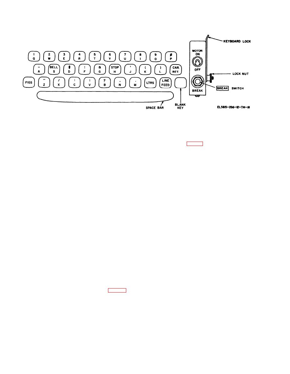
Adjusting Motor Speed (Not Applicable on TT-335/TG and TT-537/G) |
|
||
| ||||||||||
|
|
 TM 11-5815-206-12/ TO 31W4-2PGC1-61
Figure 2-5. Teletypewrirer TT-4(*)/TG or TT-698(*)/TG
d . Hold the vibrating end of the tuning fork
(a) S c o o p o u t a h o l e a b o u t 6 i n c h e s i n
diameter and about 6 inches deep.
close to one eye and look through the slots in the
vibrating shutter to view one of the white dots on
(b) Drive a rod vertically into the hole until
the top of the rod is approximately 3 inches below
the governor target (fig. 1-9).
e . Make no adjustment if the selected spot
the surface of the earth. Swing the driving hammer
carefully to avoid whipping of rod (whipping
appears to be motionless. If the spot appears to be
results in poor contact between the rod and the
moving clockwise, pull the end of the governor
soil).
adjustment worm outward. Release the worm when
t h e apparent clockwise motion of the spot has
(C) connect one end of a ground lead to the
stopped. If the spot appears to be moving
ground rod. Be sure to obtain a good bond be-
counterclockwise, push the end of the governor
tween the rod and the lead. Connect the other
adjustment worm i n w a r d u n t i l t h e a p p a r e n t
end of the lead to the pigtail on the plug of the
counterclockwise motion of the spot has stopped.
motor power cord.
To avoid overadjustment, release the worm just
(d) Saturate the earth around the top of
before the spot appears to come to a halt.
the rod with water, fill the hole around the rod
with earth, and add more water.
f. Replace the tuning fork in its storage clips on
the rear of the front door. Be sure to insert the
(e) If the soil in the area normally is not
fork between the clips and the springs. Do not
moist, drive another ground rod approximately 15
feet from the first rod and connect it to the first
insert the fork between the springs and the door.
NOTE
rod. If the soil is exceptionally dry, drive several
additional rods to form two rows of rods with a
The motor speed adjustment procedure is
minimum of ten feet between the rows and connect
the same for all operating speeds of the
the rows in parallel. Add water occasionally (daily,
teletypewriter, as described in paragraph 1-
if necessary) to maintain good contact between the
4c. If the teletypewriter is to be operated
ground rods and the soil.
a t a speed other than 60 wpm, the ap-
p r o p r i a t e worm and worm gear must be
2-8. Adjusting Motor Speed (Not Applicable on
i n s t a l l e d . This procedure is b e y o n d t h e
TT-335/TG and TT-537/G)
scope of the operator's duties and must be
a. Remove the tuning fork from the clips on the
performed by higher category maintenance
rear of the front door on the dust cover.
personnel.
Allow the motor to run for several minutes.
c . Strike the tuning fork g e n t l y a g a i n s t t h e
hand to set it into vibration.
2-6
|
|
Privacy Statement - Press Release - Copyright Information. - Contact Us |
