 |
|||
|
|
|||
|
Page Title:
Connections for Receive-Only Operation |
|
||
| ||||||||||
|
|
 TM 11-5815-206-12/ TO 31W4-2PGC1-61
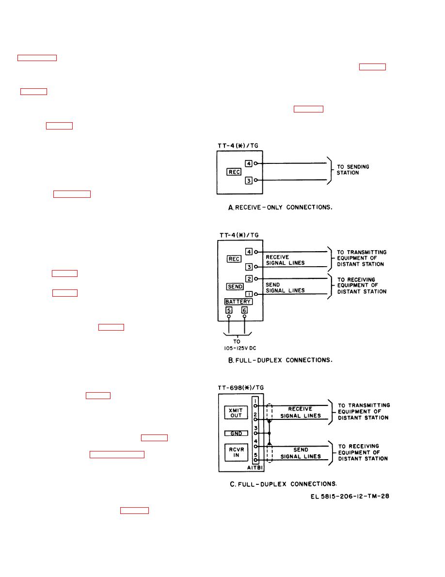
b. If power for the signal circuit is to be sup-
operation, the source of power for the signal line
plied locally, as shown on station A, part A of
normally is located at the transmitting station.
Connect one of the station's Two signal lines to
t e r m i n a l 1 and the other line to terminal 4.
terminal 3 of the line terminal board (B, fig. 2-6)
Disconnect the shorting bar from terminals 5 and 6
and the other signal line to terminal 4. Reverse the
a n d connect Power Cable Assembly CX-1202/U
c o n n e c t i o n s to terminals 3 and 4 if the C.C.
MILLIAMPERES meter pointer moves to the left
the power cable to a 105-125-volt, dc power source.
of zero.
CAUTION
Observe the C.C. MILLIAMPERES meter
s i g n a l lines to RCVR IN terminals 4 and 5 of
(A, fig. 3-1 ) when connecting the power
A1TB1.
cable to the dc power source. If the meter
pointer moves to the left of zero,
disconnect power, reverse the leads con-
nected to terminals 5 and 6, and reconnect
power.
c. If power for the signal circuit is to be sup-
plied by the distant station, as shown in station B,
part A of figure 2-7, check to be sure the shorting
b a r is connected across terminals 5 and 6 and
connect the two signal lines to terminals 1 and 4.
Reverse the signal lines if the meter pointer moves
t o the left of zero when the signal circuit is
energized.
for Half-Duplex Operation
2-12. Connections
(Voice-Frequency System) (Not Applicable to
TT-698(*)/TG)
(B, fig. 2-7)
a. Connect the shorting bar across terminals 5
and 6 (B, fig. 2-6).
b. Loosen the knurled nuts of terminals 2 and 3
a n d pivot the shorting bar that is attached to
terminal 3 away from terminal 2. Connect Cable
Assembly CX-1201/U (fig. 1-5) to terminals 1 and
2.
NOTE
Cable Assembly CX-1201/U is equipped
with a black telephone-type plug at one
end and Cable Assembly CX-1200/U has a
similar type red plug.
c. Connect Cable Assembly CX-1200/U to
terminals 3 and 4 (fig. 1-5).
d. Insert the red plug in the REC jack of the
voice-frequency equipment, and insert the black
plug into the SEND jack. Reverse the leads
connected to terminals 3 and 4 if the pointer of the
D.C. MILLIAMPERES meter (A, fig. 3-1) moves
to the left of zero when the REC signal circuit is
energized. Refer to paragraph 5-3 for additional
installation details if the voice-frequency equip-
ment is the TH-5/TG: for information on voice-
frequency equipment other than TH-5/TG, refer to
the technical manual that covers the equipment.
2-13. Connections for Receive-Only Operation
a. High Level Units (A, fig. 2 - 8 ) . W h e n a
Figure 2-8. Connections for receive-only and full-duplex operations.
teletypewriter is connected for receive-only
2-10
|
|
Privacy Statement - Press Release - Copyright Information. - Contact Us |
