 |
|||
|
|
|||
|
Page Title:
REMOVE/REPLACE RS-232C PANEL ASSEMBLY (Cont) |
|
||
| ||||||||||
|
|
 TM 11-7025-233-23
4-20. REMOVE/REPLACE RS-232C PANEL ASSEMBLY (CONT)
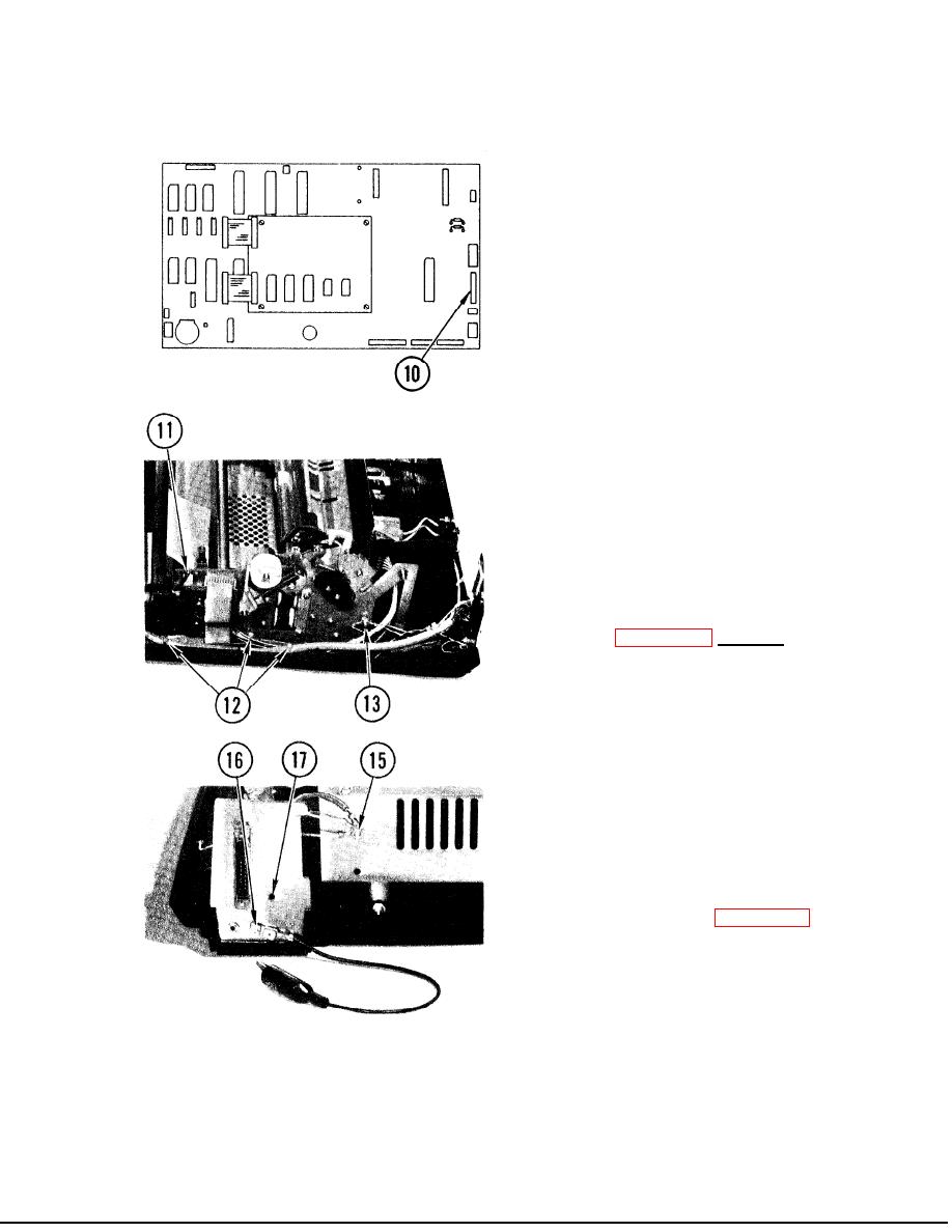
10. Connect connector P7 to logic board.
11. Connect connector to top left edge
of carriage servo drive board.
12. Install three tie wraps.
13. Connect panel assembly cable ground
wire. Tighten nut and washers.
14. Replace print position indicator
board (para 4-15, Replace, steps 2
and 4).
15. Replace panel assembly ground wire.
Replace and tighten nut, screw and
washer.
16. Replace alligator clip ground wire.
Replace and tighten screw, nut, and
washers.
17. Replace ground stud and ground wire
on ground stud. Replace and tighten
nut and washer.
18. Close up printer (para 4-11).
19. Install paper.
20. Tear off paper so only two forms
remain in printer.
21. Run self test. Make sure that
status indicater displays P-O when
paper runs out,
22. Install paper.
4-57
|
|
Privacy Statement - Press Release - Copyright Information. - Contact Us |