 |
|||
|
|
|||
|
Page Title:
REMOVE/REPLACE RS-232C PANEL ASSEMBLY (Cont) |
|
||
| ||||||||||
|
|
 TM 11-7025-233-23
4-20. REMOVE/REPLACE RS-232C PANEL ASSEMBLY (CONT)
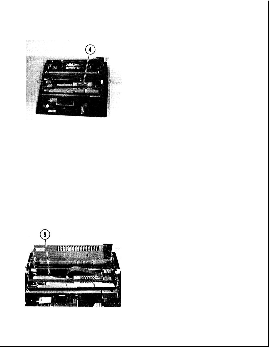
4. Lower protective covering.
5. Remove guide string from two-wire P9
cable.
6. Slide carriage assembly to far right
position.
7. Slide plastic protective cover onto
logic board so lower hooks on cover
attach to edge of board, and J9
connector pins go through two small
holes in front of cover.
8. Insert connector P9 into plastic
protective cover and connect to
connector J9 on logic board, as
shown.
9. Lower protective covering.
4-56
|
|
Privacy Statement - Press Release - Copyright Information. - Contact Us |