 |
|||
|
|
|||
|
Page Title:
INSTALLING PRINT SYSTEM ASSEMBLY (cont) |
|
||
| ||||||||||
|
|
 TM 11-7025-217-30
NOTE
Apply retaining compound (item 6,
Appx B) to threads of Screws in
steps 6, 9, 10, and 13.
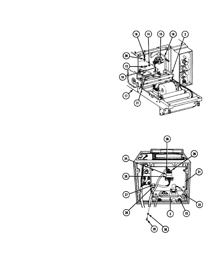
6. Install two screws (13), flatwashers (14)
and interlock switch (15) on right side
plate (16).
7. Carefully slide printer mechanics
subassembly (2) into chassis (17).
8. Tighten two screws (18) to secure
bottom plate of printer mechanics
subassembly (2) to chassis (17).
9. Install four screws (19), flatwashers
(20), and protective cover (21 ).
10. Install two screws, flatwashers,
and Iockwashers (22) on rear
of motherboard (3).
11. Tighten two screws (23) through
cutouts at rear of print system
motherboard (3).
12. Aline connector P10(24) with
connector J10(25) and tighten two
screws (26), two turns at a time,
until tight.
2-103
|
|
Privacy Statement - Press Release - Copyright Information. - Contact Us |