 |
|||
|
|
|||
|
|
|||
| ||||||||||
|
|
 TM 11-5805-387-20-2
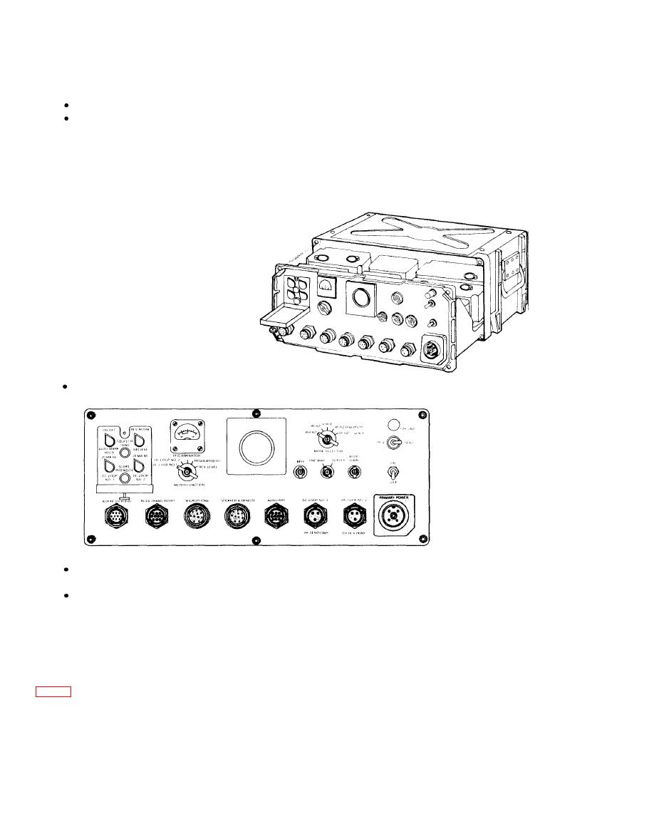
d. Replacing Modem Chassis into Case
Follow procedure given below:
Be sure modem case is top side up. (Four depressions on top of case.)
Grasp chassis by raised ribbed frame (not components); begin sliding chassis into case. When
about 1 inch of chassis remains outside case, maneuver chassis until it engages guide prongs
at back of case. Slide chassis into case.
Alternately tighten six captive holddown screws around outside edge of front panel.
Reconnect any cables that may have been removed. Remove temporary cable labels. Be
sure all cables fit tightly in their correct sockets.
Tighten six screws.
2-12. TESTING
Locate faulty components mounted on front panel and check for shorts at the power connector.
2-13. PAINTING
Remove rust and corrosion from metal surfaces by lightly sanding with fine sandpaper (item 4,
app. C). Brush two thin coats of the proper paint on bare metal to protect it from further corrosion.
Refer to applicable procedures in TB 43-0118.
2-14. ADJUSTMENT
Check front panel controls to be sure that they operate freely.
|
|
Privacy Statement - Press Release - Copyright Information. - Contact Us |