 |
|||
|
|
|||
|
Page Title:
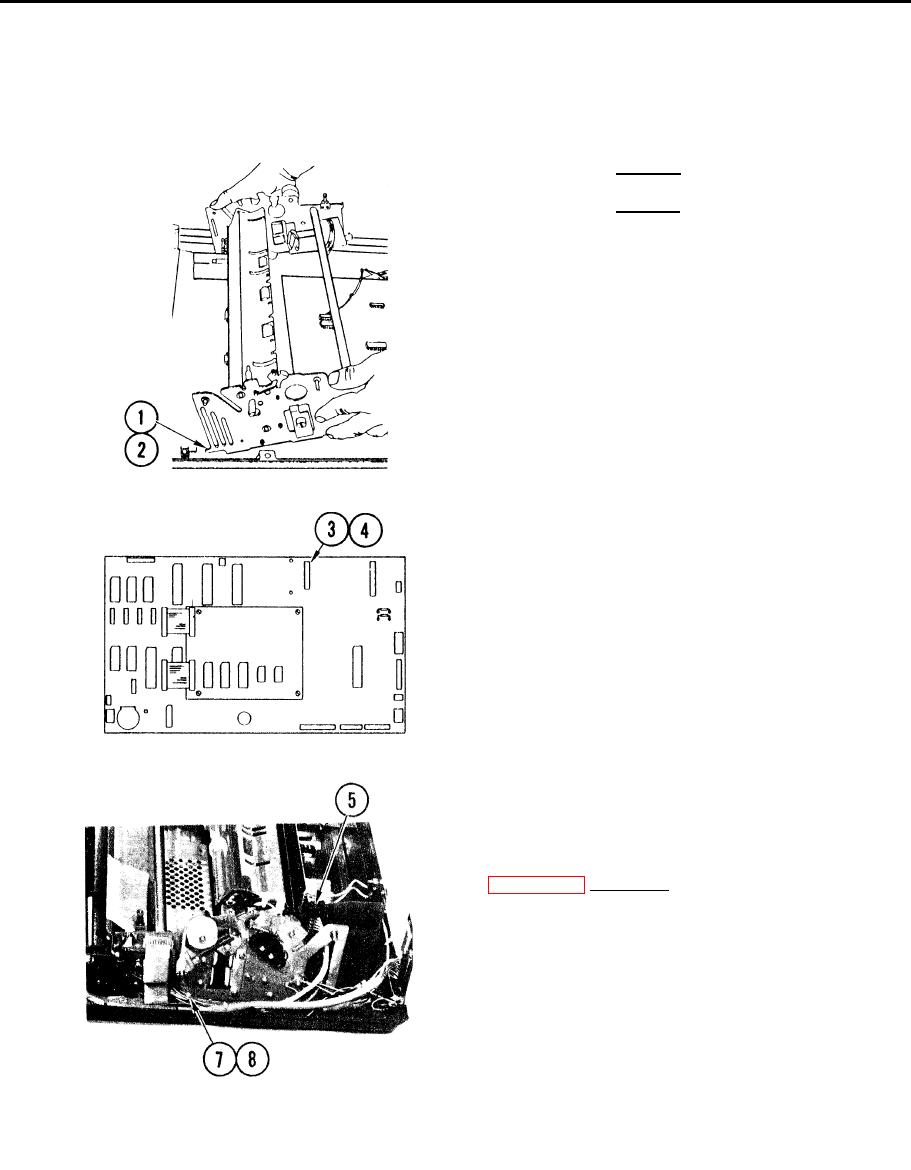
REMOVE/REPLACE FRAME AND DRIVE ASSEMBLY (CONT) |
|
||
| ||||||||||
|
|
 TM 11-7025-233-23
4-23. REMOVE/REPLACE FRAME AND DRIVE ASSEMBLY (CONT)
Replace
CAUTION
Ensure no loose cables are caught
under frame and drive assembly when
it is placed on bottom cover.
1. Facing front of printer, grasp each
side of frame and drive assembly.
Slide forward until tabs set into
bottom cover lugs.
2. Set bottom tabs into mating slots in
bottom cover.
3. Connect print head ribbon cable at
J2 on logic board.
4. Press print head ribbon cable
retainers down on plastic standoffs
until they snap into place.
5. Insert power supply cable connector
J2 throuqh hole in side frame and
connect to P2 on power supply board
6. Lift up front of frame and drive
assembly.
7, Thread paper stepper motor cable
connector J1O through cutout in side
frame.
8. Install tie wrap securing paper
stepper motor cable,
4-64
|
|
Privacy Statement - Press Release - Copyright Information. - Contact Us |
