 |
|||
|
|
|||
|
Page Title:
REMOVE/REPLACE FRAME AND DRIVE ASSEMBLY (CONT) |
|
||
| ||||||||||
|
|
 TM 11-7025-233-23
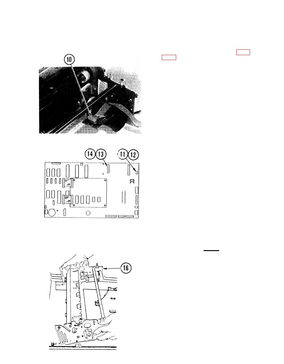
4-23. REMOVE/REPLACE FRAME AND DRIVE ASSEMBLY (CONT)
9. Remove side frame support (para
10. Tag and disconnect encoder cable
connector from P1 on encoder board.
11. Tag cable to paper drive motor at
P1O on logic board.
12. Lift front of frame and drive
assembly, and disconnect cable
connector at P1O on logic board.
13. Using pliers, squeeze each plastic
standoff to free print head ribbon
cable retainer.
14. Tag and disconnect print head ribbon
Cable at J2 on logic board.
15. Cut tie wrap securing paper stepper
motor cable.
CAUTION
Use care to ensure no cables are
snagged when removing the frame and
drive assembly.
16. Facing front of printer, grasp each
side of frame and drive assembly and
lift up and back to remove.
4-63
|
|
Privacy Statement - Press Release - Copyright Information. - Contact Us |
