 |
|||
|
|
|||
|
Page Title:
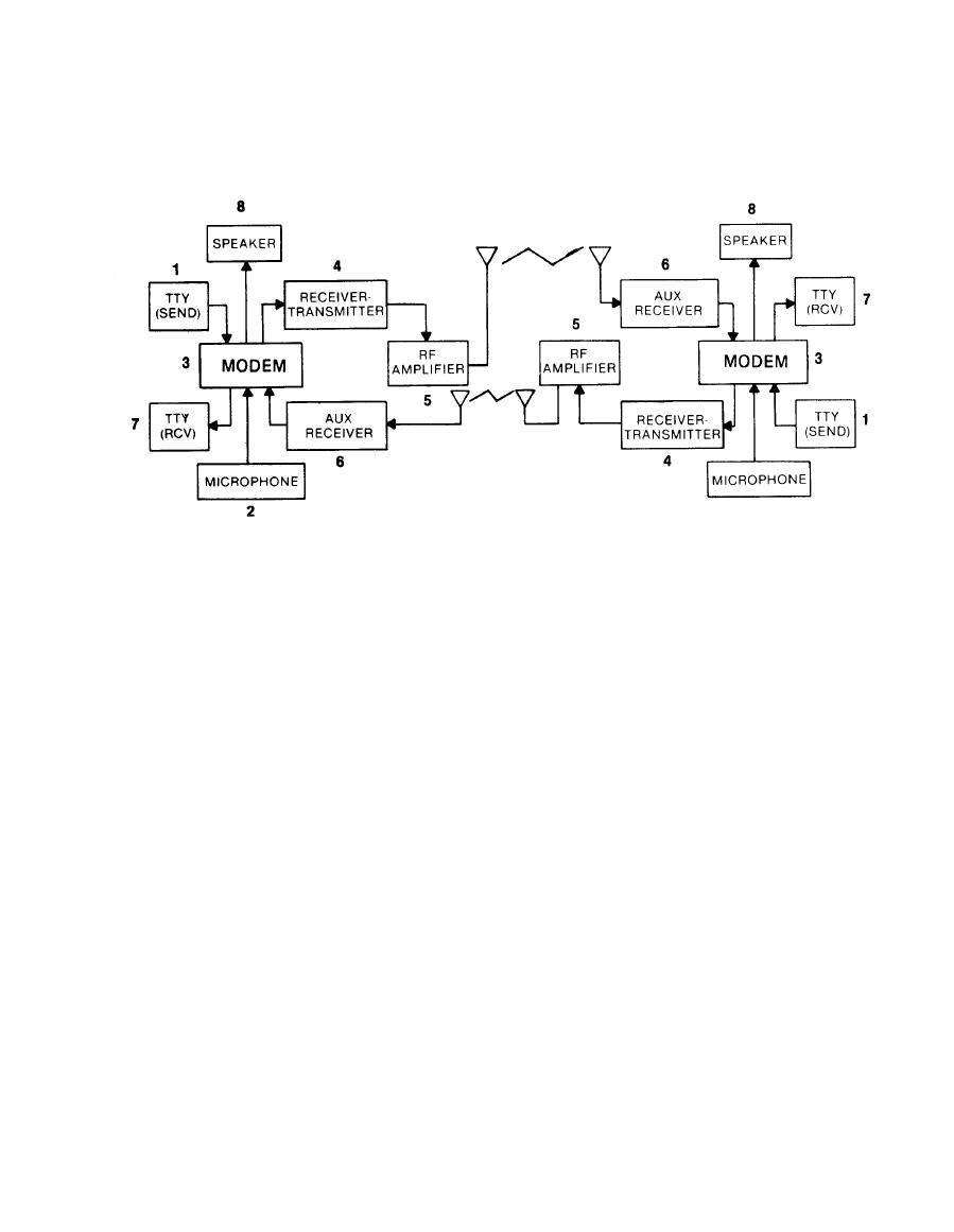
FIGURE 1-1. MODEM: TYPICAL CONFIGURATION FOR DUPLEX RADIO TELETYPEWRITER SYSTEM |
|
||
| ||||||||||
|
|
 TM 11-5805-387-20-2
TELETYPEWRITER SYSTEM
1 Teletypewriter [tty (SEND)] dc mark and space pulses are sensed by the modem.
2 The modem also senses voice signals from microphone.
3 Teletypewriter dc pulses are converted to tty tones and combined with voice signals by the modem.
4 These combined tty tones and voice signals are applied to a receiver-transmitter, and converted to
an rf signal.
5 This rf signal is then applied to an rf amplifier for transmission. The amplified rf signal is applied to
an antenna and sent to a distant station.
6 When received, rf signals are processed by an aux (auxiliary) receiver and applied to the modem.
The signals are separated and converted into voice signals and tty mark and space pulses.
7 The tty pulses are applied to a teletypewriter [tty (RCV)] and then applied to page printers or tape
punches for message interpretation.
8 An audio output can be applied to speaker for local use.
1-3
|
|
Privacy Statement - Press Release - Copyright Information. - Contact Us |
