 |
|||
|
|
|||
|
Page Title:
REMOVE/REPLACE POWER SUPPLY CABLE (CONT) |
|
||
| ||||||||||
|
|
 TM 11-7025-233-23
4-47. REMOVE/REPLACE POWER SUPPLY CABLE (CONT)
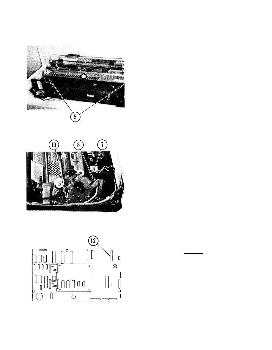
5. Loosen screws.
6. Slide cover in direction shown, and
lift off.
7. Remove protective bracket.
8. Disconnect cable connector P2 on
power supply board.
9. Thread cable and cable connector
through hole in side frame.
10.Cut tie wrap.
11. Lift up front of frame and drive
assembly.
12. Disconnect cable connector at P8 on
logic board.
13. Remove cable.
Replace
1.Lift up front end of frame and drive
assembly.
2. Insert J8 connector end of cable
under frame and drive assembly, and
thread under servo drive board and
encoder assembly.
4-118
|
|
Privacy Statement - Press Release - Copyright Information. - Contact Us |