 |
|||
|
|
|||
|
Page Title:
REMOVE/REPLACE CARRIAGE ASSEMBLY |
|
||
| ||||||||||
|
|
 TM 11-7025-233-23
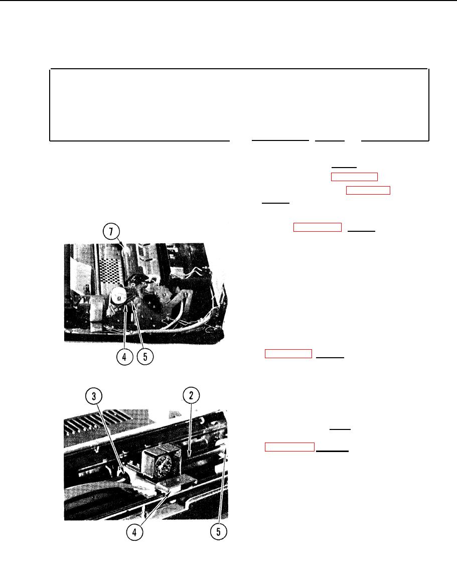
4-30. REMOVE/REPLACE CARRIAGE ASSEMBLY
INITIAL SETUP
Common Tools
Special Tools
q Dowel pins
q Tool kit
Remove
1. Access printer (para 4-11).
2. Remove print head (para 4-17,
Remove, steps 3-10).
3. Remove carriage assembly left idler
pulley (para 4-33, Remove, steps
3-7).
4. Remove spring from run-load lever on
right side frame.
5. Remove screw from rear rail on right
side and lift off run-load lever and
right eccentric.
6. Slide rail to left, and lift up.
7. Remove right carriage bumper.
8. Remove carriage assembly drive belt
9. Remove carriage assembly from
printer.
10. Slide ribbon cable out of groove in
cartridge.
Replace
1. Replace carriage assembly drive belt
2. Slide rail to left and lift up.
3. Insert rail through holes in
carriage assembly.
4. Mount carriage assembly clevis on
front rail.
5. Place right carriage bumper on rear
carriage rail.
4-75
|
|
Privacy Statement - Press Release - Copyright Information. - Contact Us |
