 |
|||
|
|
|||
|
Page Title:
REMOVE/REPLACE FRAME AND DRIVE ASSEMBLY |
|
||
| ||||||||||
|
|
 TM 11-7025-233-23
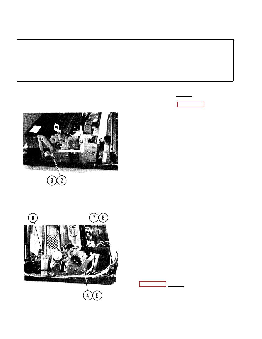
4-23. REMOVE/REPLACE FRAME AND DRIVE ASSEMBLY
INITIAL SETUP
Materials/Spare Parts
Common Tools
q Tool kit
q Tags
q Pen or pencil
Remove
1. Access printer (para 4-11).
2. At left rear corner of printer
loosen nut on RF cable grounding
stud.
3. Remove RF cable from frame.
4. At right rear corner of printer,
loosen nut on grounding stud.
5. Remove RF cable and all ground wires
from frame.
6. Tag and remove ribbon cable connector
from carriage servo drive board.
7. Tag and remove cable from connector
on side of power supply assembly
8. Pull cable free of frame.
4-62
|
|
Privacy Statement - Press Release - Copyright Information. - Contact Us |