 |
|||
|
|
|||
|
Page Title:
REMOVE/REPLACE SIDE FRAME SUPPORT (CONT) |
|
||
| ||||||||||
|
|
 TM 11-7025-233-23
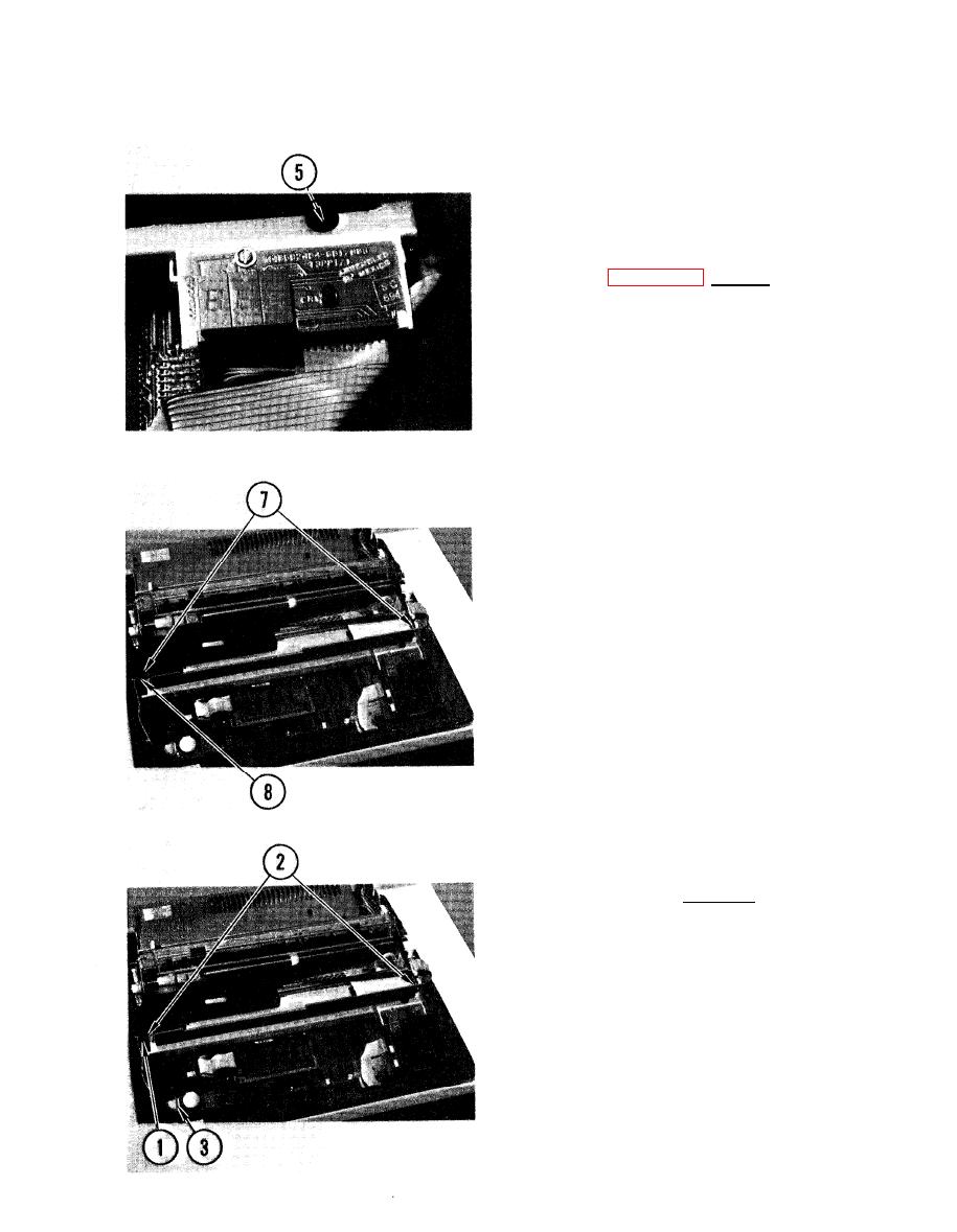
4-21. REMOVE/REPLACE SIDE FRAME SUPPORT (CONT)
5. Remove right retaining screw from
frame support.
6. Remove print position indicator
board (para 4-15, Remove, steps 3-5).
7. Lift frame support off mounting tabs.
8. While lifting frame support out of
printer, carefully feed ribbon motor
cable throuqh cutout in side frame.
REPLACE
1. Carefully route ribbon motor cable
through cutout in side frame.
2. Position frame support on mounting
tabs.
3. Connect protective cover and cable
connector P11 to logic board.
4-59
|
|
Privacy Statement - Press Release - Copyright Information. - Contact Us |