 |
|||
|
|
|||
|
Page Title:
TESTING POWER SUPPLY OUTPUT |
|
||
| ||||||||||
|
|
 TM 11-7025-217-30
2-14.
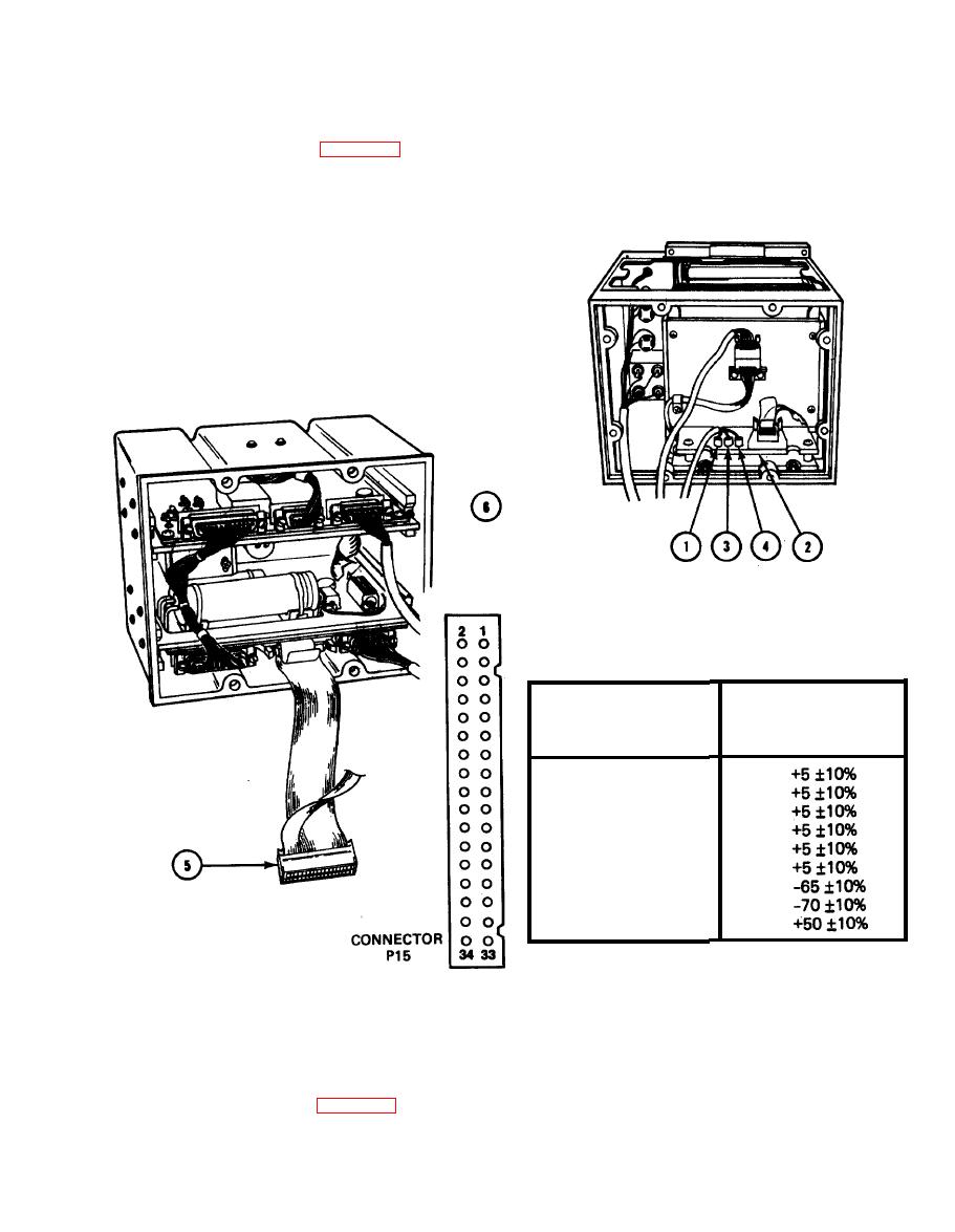
TESTING POWER SUPPLY OUTPUT
Remove logic board (para 2-54), but do not disconnect connectors P15 and P16.
1,
Connect negative (-) lead of DMM to stud terminal E5(1) on print system motherboard (2).
2
Connect printer to power.
3
4, Set POWER ON/OFF circuit breaker to ON.
Using DMM positive (+) lead, check power
5.
supply output voltages on stud terminals
E6(3), E7(4), and connector P15(5). Check
output voltage on rear lead of resistor
R37(6) while pressing and holding PAPER
ADV switch.
TABLE 2-1. POWER SUPPLY OUTPUT
VOLTAGES
Connector-Pin
Voltage
or
Stud Terminal
P15-16
P15-18
P15-20
P15-21
P15-22
P15-23
E6
E7
R37-RearLead
Set POWER ON/OFF circuit breaker to OFF.
6.
Disconnect printer from power.
7.
Remove DMM negative lead (-) from stud terminal E5(1).
8.
Install logic board (para 2-55).
9.
2-57
|
|
Privacy Statement - Press Release - Copyright Information. - Contact Us |