 |
|||
|
|
|||
|
Page Title:
Section Il. EQUIPMENT DESCRIPTION AND DATA |
|
||
| ||||||||||
|
|
 TM 11-7025-217-30
1-5, NOMENCLATURE CROSS-REFERENCE LIST (Continued)
Official Nomenclature
Common Name
Logic Board Assembly
Logic Board
Print System Interconnect PWB
Motherboard
DC Power Supply
Power Supply
Printhead Assembly
Printhead
Console Machining
Chassis
1-6. REPORTING EQUIPMENT IMPROVEMENT RECOMMENDATIONS (EIR)
If your printer needs improvement, let us know. Send us an El R. You, the user, are the only one who can
tell us what you don't like about your equipment. Let us know why you don't like the design. Put it
on an SF 368 (Quality Deficiency Report). Mail it to Commander, US Army Communications
Electronics Command and Fort Monmouth, ATTN: AMSEL-ME-MP, Fort Monmouth, New Jersey 07703-5007.
we'll send you a reply.
Section Il. EQUIPMENT DESCRIPTION AND DATA
1-7. EQUIPMENT CHARACTERISTICS
Refer to TM 11-7021-201-12, Chapter 1, for equipment characteristics,
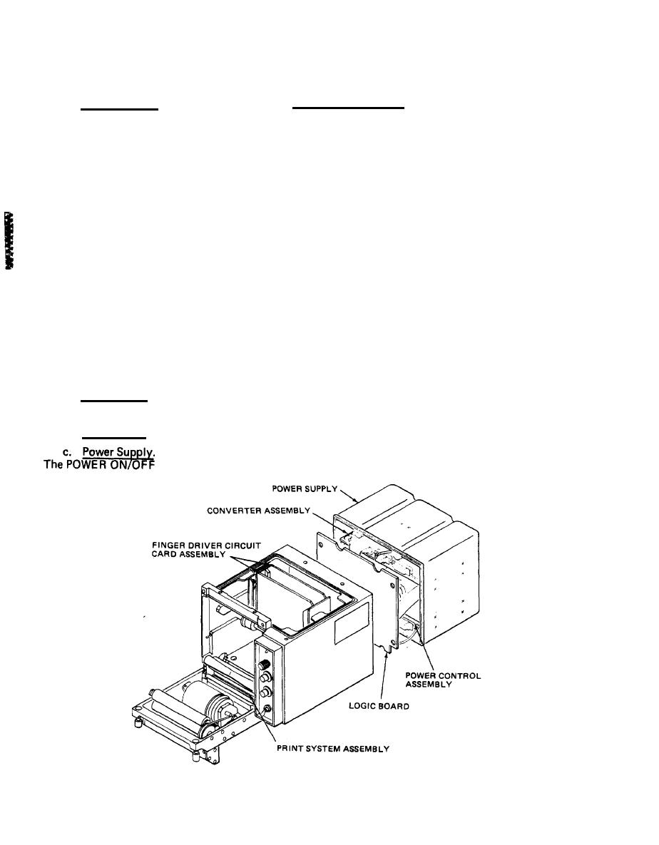
1-8. LOCATION AND DESCRIPTION OF MAJOR COMPONENTS
a. Print Section. The print section finger driver circuit card and print system assemblies provide data
paths and control logic necessary to print the data on paper.
b. Logic Board. The logic board consists of electronics which control printer functions.
The power supply provides all dc voltages needed for operation of the equipment.
circuit breaker, located on the control panel, provides voltage overload protection.
1-2
|
|
Privacy Statement - Press Release - Copyright Information. - Contact Us |