 |
|||
|
|
|||
|
Page Title:
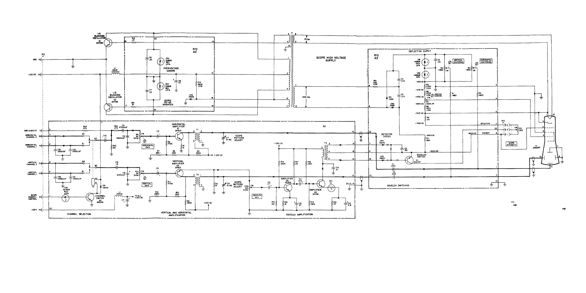
Figure FO-14. Scope A2 Module, Schematic Diagram. |
|
||
| ||||||||||
|
|
 TM 11-5805-387-34-2
NOTES:
4
HEAVY LINE
INDICATES MAIN SIGNAL PATH. CLOSED
1.
FOR COMPLETE REFERENCE DESIGNATOR, PREFIX
PARTIAL REFERENCE DESIGNATORS WITH SUBASSEMBLY
ON SIGNAL PATH INDICATES AC SIGNAL
DESIGNATOR AND SCOPE MODULE DESIGNATOR A2.
SUCH AS FSK AND NSK TONES. OPEN ARROWHEAD
INDICATES VARYING DC, OR DC PULSES.
2.
UNLESS OTHERWISE SPECIFIED, RESISTOR VALUES ARE
IN OHMS, CAPACITORS IN MICROFARADS.
3.
HIGH VOLTAGE DC MEASUREMENTS ARE MADE WITH
RESPECT TO GROUND USING DC SCOPE AND HIGH
VOLTAGE AC PROBE. OUTPUT OF T1 WAS MEASURED
Figure FO-14. Scope A2 Module, Schematic Diagram.
PEAK-TO-PEAK WITH SAME SCOPE AND PROBE.
|
|
Privacy Statement - Press Release - Copyright Information. - Contact Us |
