 |
|||
|
|
|||
|
|
|||
| ||||||||||
|
|
 TM 11-5805-387-34-2
TEST POINT CHART 2 - Continued
TEST POINT
MODEM INPUT
MODEM SWITCH SETTING
INDICATION
19. FL7-1
2,805 Hz, 2.45 volts rms
MODE SELECTOR: 850 HZ
275 mv rms 50
at J1-A.
20.
FL7-3
2,805 Hz, 2.45 volts rms
MODE SELECTOR: 850 HZ
110 mv rms 30
at J1-A.
21.
R2 (cw
No input needed.
MODE SELECTOR: 850 HZ
20.0 volts dc
terminal)
0.5
22.
R2
No input needed.
MODE SELECTOR: 850 HZ (BFO
3.6 volts p-p 0.6
(center
fully ccw)
terminal)
23.
R2
No input needed.
MODE SELECTOR: 850 HZ (BFO
20.0 volts do
(center
fully cw)
0.5
terminal)
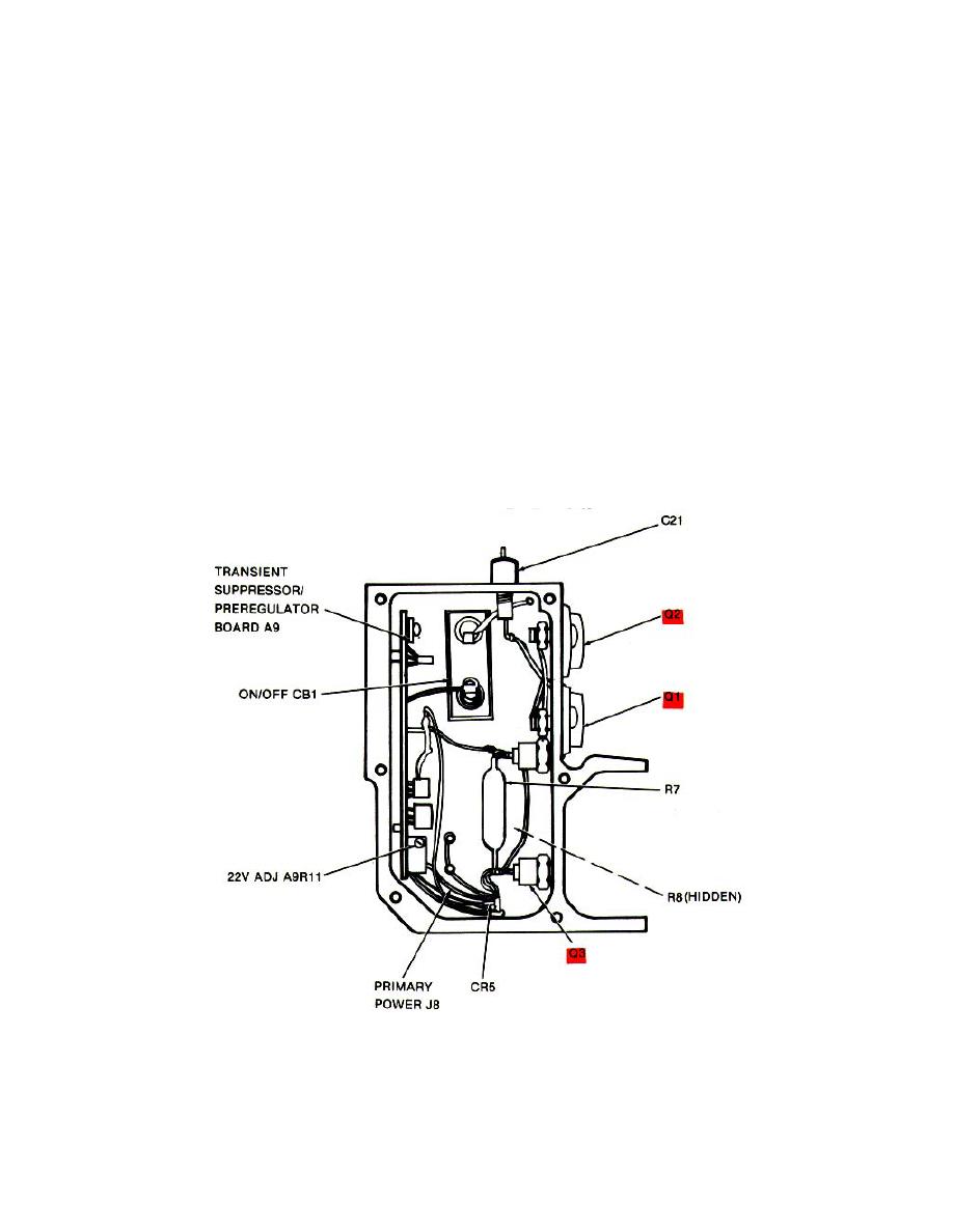
TEST POINT CHART 3
TEST POINT
EMITTER
BASE
COLLECTOR
Q1
23 1 volts
22.4 1 volts
27 1 volts
Q2
23 1 volts
22.4 1 volts
27 1 volts
Q3
26.3 1 volts
27 1 volts
23 1 volts
3-21
|
|
Privacy Statement - Press Release - Copyright Information. - Contact Us |
