 |
|||
|
|
|||
|
|
|||
| ||||||||||
|
|
 TM 11-5805-387-34-2
MALFUNCTION/SYMPTOM
PROBABLE CAUSE
TEST PROCEDURE
INDICATION
YES
NO
Do all continuity and resistance checks with all power removed.
4. With power source removed and ON/OFF
Continuity
----------------
Replace
switch in ON position, connect ME-26B/U
defective
between terminal A of connector J8 and
connector J8
terminal 1 of board A9. Check for
continuity.
(3) NO +20 VOLTS DC METER INDICATION
Defective: Meter M1. Meter function switch S3.
Circuit board A7.
1. Connect ME-26B/U between meter M1
+20 vdc
Replace
Go to 2.
posts.
defective
meter M1
2. Check continuity of METER FUNCTION
Continuity
Go to 3.
Replace
switch (fig. FO-8).
defective
switch S3
3. Connect ME-26B/U across pin 13 of XA1;
+22 vdc
Go to 4.
Replace
measure voltage.
defective
wiring.
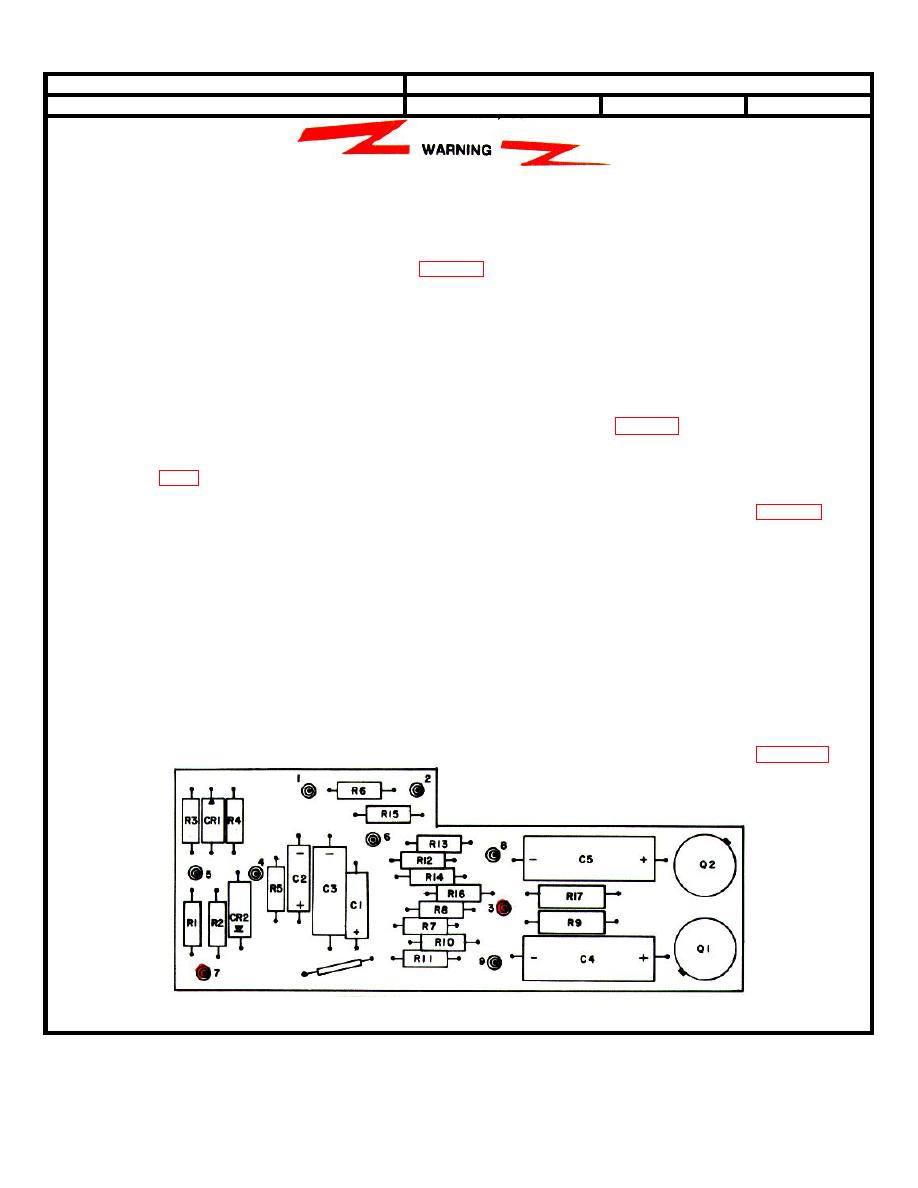
4. Remove cover of circuit board A7 by
+20 vdc
Continue test. Continue test.
removing three screws and three washers.
0.2
Connect ME-26B/U across terminal 3;
measure voltage.
Connect ME-26B/U across terminal 7;
+0.06 vdc
------------
Replace
measure voltage.
defective
board A7
3-5
|
|
Privacy Statement - Press Release - Copyright Information. - Contact Us |
