 |
|||
|
|
|||
|
Page Title:
NO RCV LEVEL READING ON METER M1. RECEIVE CHANNEL MALFUNCTIONING |
|
||
| ||||||||||
|
|
 TM 11-5805-387-34-2
MALFUNCTION/SYMPTOM
PROBABLE CAUSE
NO
TEST PROCEDURE
INDICATION
YES
3. Remove transmitter module A3. Check
Continuity
Go to 4.
Replace
continuity of 50-ohm mike keying circuit
defective
components external to module A3: diode
component.
CR4, RCV/SEND switch S5, circuit board
A6, feed through capacitors C4, C9, C17,
C18 (fig. FO-11).
4. Connect AN/USM-207 across terminal 1 of
200-2,300 Hz
Continue test
Go to 5.
filter FL3. Speak into mike.
Connect AN/USM-207 across terminal 3 of
200-2,300 Hz
------------------
Replace
filter FL3. Speak Into mike.
defective filter
FL3 (para 3-9).
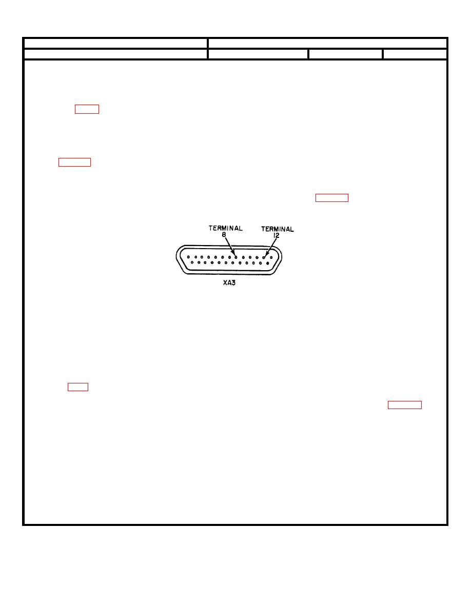
5. Connect ANIUSM-281 between terminal 8
Mike Input
Replace
--------------------
(ground) of XA3 and terminal 12 of XA3.
signal
module A3
present.
(8) NO RCV LEVEL READING ON METER
Defective: One way-duplex switch S1
M1. RECEIVE CHANNEL MALFUNC-
TIONING
NOTE
There will be no RCV LEVEL indication when using test cable No. 3.
Check continuity of ONE WAY/DUPLEX
Continuity
---------------
Replace
switch (fig. FO-8).
defective
switch S1
2-16
|
|
Privacy Statement - Press Release - Copyright Information. - Contact Us |