 |
|||
|
|
|||
|
Page Title:
MODEM NOT TRANSMITTING EITHER VOICE OR TTY. |
|
||
| ||||||||||
|
|
 TM 11-5805-387-34-2
MALFUNCTION/SYMPTOM
PROBABLE CAUSE
TEST PROCEDURE
INDICATION
YES
NO
(5) MODEM NOT TRANSMITTING EITHER
Defective: Transmitter module A3. Circuit board A6.
VOICE OR TTY.
RCV-SEND switch S5.
1. With TS-799A/UGM-1 and test cable no. 3
Go to 2.
Replace
connected (para 2-4) make the
defective
following tests across OUTPUT of
module A3
transmitter module A3 (internal NORM/REV
switch at NORM) with the AN/USM-207:
MODE SELECTOR switch
850 Hz
SPACE: 2,425 Hz 25
MARK: 1,575 Hz 25
85-Hz modes
SPACE: 2,847.5 Hz 2
MARK: 2,762.5 Hz 2
VOICE
200-2,400 Hz
Do all continuity and resistance checks with all power removed.
2. Connect ME-26B/U between pin 1 of XA3
Continuity
Go to 3.
Replace
and terminal 2 of board A6; check for
defective
continuity.
wiring.
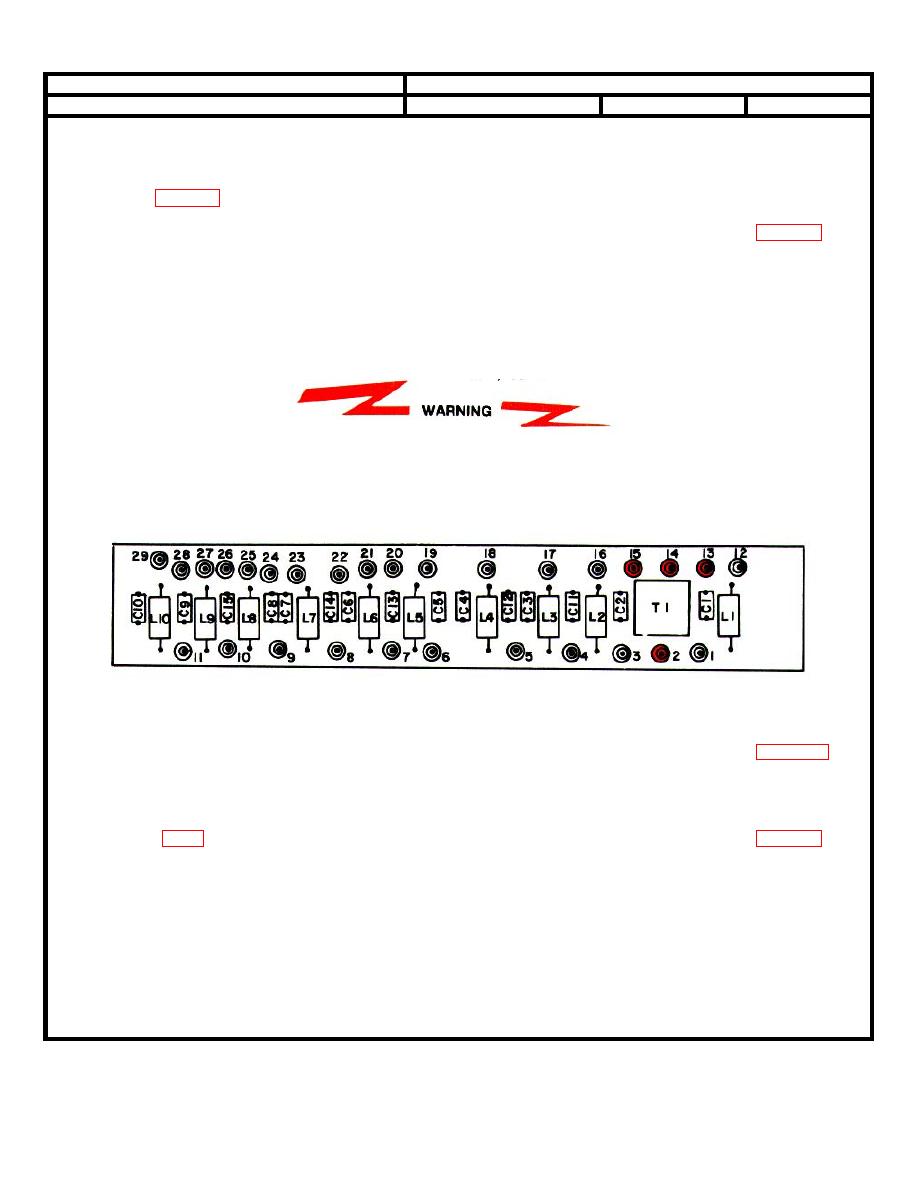
3. Check for continuity between terminals 2
Continuity
Go to 4.
Replace
and 13 of board A6; between terminals 14
defective
and 15 of board A6.
board A6
4. Set RCV/SEND switch to SEND.
Continuity
--------------
Replace
Connect ME-26B/U between SEND
defective
POST and CENTER POST. Check for
switch S5
continuity. (fig. FO-8)
2-13
|
|
Privacy Statement - Press Release - Copyright Information. - Contact Us |