 |
|||
|
|
|||
|
|
|||
| ||||||||||
|
|
 TM 11-5805-387-34-2
1-43. TRANSMITTER MODULE A3
(fig. FO-10)
General. Transmitter module A3 contains tty signal (mark and space tones) generation circuitry, transmit voice
circuits, and output amplifying circuits.
Tty Signal Generation. Mark and space tone signals are derived from oscillators with outputs that are switched by
associated switching circuitry and divided to the proper frequency by divider circuits. Depending on the mode of
operation, the outputs are mixed in various combinations to develop the proper output frequency.
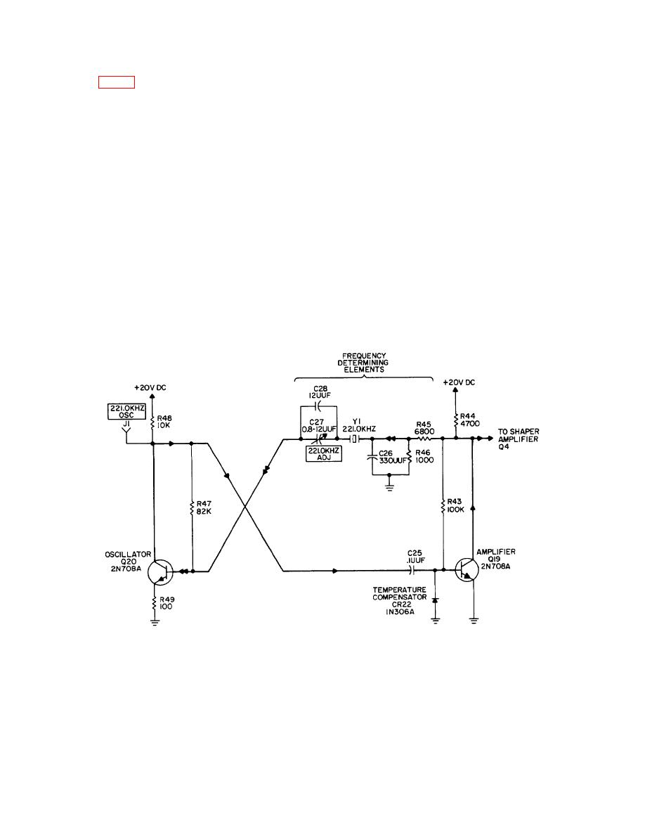
Mark oscillator. Oscillator A3A1Q19, Q20 provides the fundamental frequency used to generate a mark tone.
The circuit consists of a modified astable multivibrator that has a crystal in the feedback path to sustain
oscillations at the desired frequency. Frequency of operation is determined by crystal A3A1Y1, operating in the
series-resonant mode. The feedback path is through coupling resistor A3A1R45, crystal A3A1Y1, and series
capacitor A3A1C28 to the base of transistor A3A1Q20. Trimmer capacitor A3A1C27 allows slight pulling of the
oscillator frequency to compensate for circuit parameters. Resistor A3A1R46 and capacitor A3A1C26 form a
resistance-capacitance (rc) network, which assures that the crystal starts in its fundamental series-resonant
mode. The resulting 221.0-kHz signal that is developed across collector load resistor A3A1R44 is applied to
shaper amplifier A3A1Q4 through isolation diode A3A1CR3.
MARK (221.0 kHz) OSCILLATOR
NOTES:
1.
PREFIX PARTIAL REFERENCE DESIGNATORS WITH A3A1
2.
RESISTOR VALUES ARE IN OHMS.
3.
MAIN SIGNAL FLOW IS INDICATED BY HEAVY LINE AND
ARROWHEAD→ ;FEEDBACK BY DOUBLE ARROWHEAD← ←
4.
227.8KHZ(SPACE)OSCILLATOR A3A1,Q21,Q22 IS IDENTICAL TO
THIS SCHEMATIC EXCEPT FOR FREQUENCY DETERMINING
ELEMENTS AND REFERENCE DESIGNATORS
1-32
|
|
Privacy Statement - Press Release - Copyright Information. - Contact Us |