 |
|||
|
|
|||
|
|
|||
| ||||||||||
|
|
 TM 11-7025-233-23
2-7. CARRIAGE MECHANISM
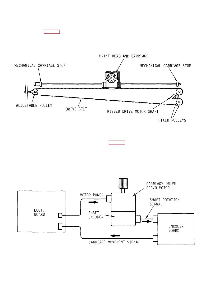
The carriage (fig. 2-3) on which the print head mounts is attached to a drive belt
spanning the width of the teleprinter. Two fixed pulleys on the right side wrap
the drive belt around the motor shaft. The shaft is ribbed to engage ribs on the
belt to prevent slip. Belt slippage at the carriage or motor would cause the
electronics to lose control of the carriage and its position.
Figure 2-3.
Carriage Mechanism
The single pulley on the left side is mounted on an adjustable bracket. The
adjustment is used for belt removal and belt tension control.
In the carriage drive and control circuit, (fig. 2-4), the drive motor is a dc
servo type, turning in either direction the amount specified by the logic board.
An encoder on the motor shaft has board-mounted circuitry to translate shaft
rotation and direction into coding used to determine and remember carriage
position. The encoder board also includes the circuitry which controls character
spacing. Character spacing is operator selected. The encoder board also has
circuits used by the paper drive. The encoder board is an integral part of the
encoder and is not replaceable in the field.
Figure 2-4.
Carriage Drive Control
2-4
|
|
Privacy Statement - Press Release - Copyright Information. - Contact Us |
