 |
|||
|
|
|||
|
|
|||
| ||||||||||
|
|
 TM 11-7025-217-30
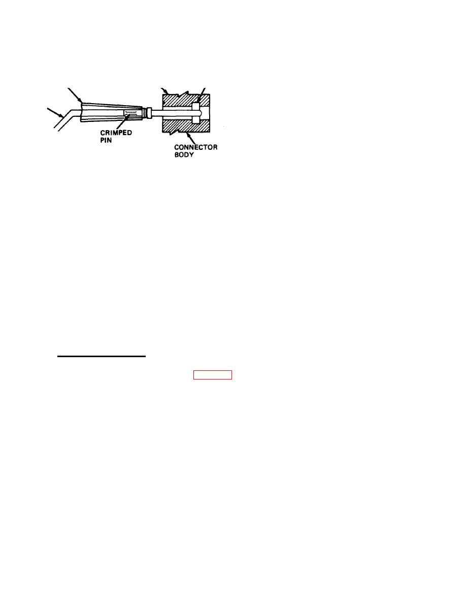
6. Cut off damaged pin insert as close to
crimped end as possible.
TIP OF
INSTALLING
LOCKING
WIRING
TOOL
GROOVE
\
SIDE
7. Strip 3/32 to 1/8 inch of insulation from
end of wire.
WIRE
8. Put replacement pin insert on stripped
end of wire.
9. Crimp pin insert.
10. Place wire with attached pin insert in
tip of INSTALLING TOOL, as shown.
NOTE
The INSTALLING TOOL is inset into connector the same
depth as the REMOVAL TOOL.
11, Install pin insert into connector.
12. Give wire a slight pull to make sure pin insert is locked in place.
13. Replace cable tie.
c. Installing 1/0 Connector.
1. Install input data cable assembly (para 2-71).
2-122
|
|
Privacy Statement - Press Release - Copyright Information. - Contact Us |
