 |
|||
|
|
|||
|
Page Title:
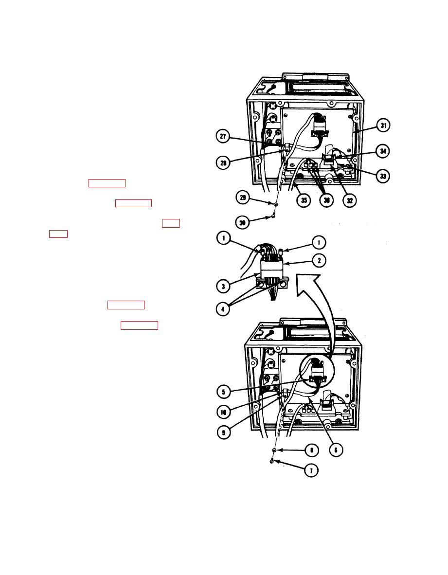
REMOVING MOTOR HARNESS ASSEMBLY |
|
||
| ||||||||||
|
|
 TM 11-7025-217-30
Install loop clamp (27), loop washer
13.
(28), four flatwashers (29),
four screws (30), and back plate (31).
14. Aline and mate connector P17(32) with
connector J17(33). Close two retain-
ing arms to secure connectors.
15. Connect three power cable (35) leads
to three stud terminals E5, E6, and
E7 (36) as tagged. Remove tags.
16.
Install finger drive circuit card
assemblies (para 2-59).
17.
Install logic board (para 2-55).
18. Perform printhead pressure test (para
Load paper supply. (Refer to
19.
TM 11-7021-201-12.)
2-62. REMOVING MOTOR HARNESS ASSEMBLY
1. Separate chassis (para 2-30).
2. Remove logic board (para 2-54).
3. Loosen two screws (1), turning each
screw two turns at a time, until con-
nector P10(2) can be removed from
connector J10(3).
4. Remove two nuts (4) and connector
J10(3) from mounting bracket (5).
5. Tag and cut wires of harness (6) from
connector J10(3).
6. Remove screw (7), flatwasher (8), loop
washer (9), and loop clamp (10).
2-104
|
|
Privacy Statement - Press Release - Copyright Information. - Contact Us |
