 |
|||
|
|
|||
|
Page Title:
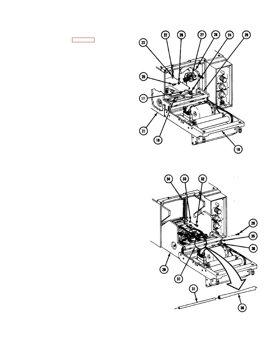
REMOVING PRINT SYSTEM ASSEMBLY (cont) |
|
||
| ||||||||||
|
|
 TM 11-7025-217-30
Remove finger driver circuit card
11.
assemblies (para 2-58).
Loosen completely two screws (17)
12.
through access holes in protective cover
(18).
13. Grasp door (19) and carefully slide
printer mechanics subassembly (20) out
of chassis (21).
Remove four screws (22), four flat-
14.
washers (23), and protective cover (18).
Remove four threaded standoffs (24).
15.
Remove two screws (25), two flat-
16.
washers (26), and interlock switch (27)
from right side plate (28).
Remove two screws (29), tracking bar
17.
(30), and rod (31) from printer
mechanics subassembly (20); using a
1/16-inch drift pin, drive rod (31) out
of tracking bar (30).
18.
Remove four screws (32), four flat-
washers (33), and protective plastic (34).
Remove two screws (35) and print-
19.
head stop (36) from both sides of
printer mechanics subassembly (20).
CAUTION
Exercise care in removing print system
assembly from the printer. This
assembly can be easily damaged by
careless mishandling or use of undue
force.
20. Carefully remove print system assembly
(37) from printer mechanics sub-
assembly (20).
2-101
|
|
Privacy Statement - Press Release - Copyright Information. - Contact Us |
