 |
|||
|
|
|||
|
|
|||
| ||||||||||
|
|
 TM 11-7025-217-30
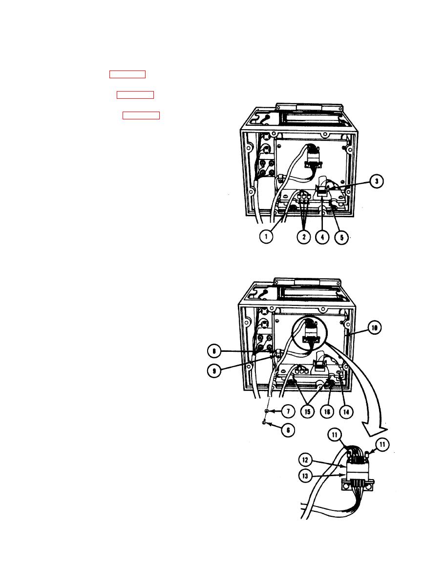
2-60. REMOVING PRINT SYSTEM ASSEMBLY
1. Separate chassis (para 2-30).
2. Remove top cover (para 2-26).
3. Remove logic board (para 2-54).
4. Tag three power cable (1) leads, than
disconnect from three stud terminals
E5, E6, and E7 (2).
5. Open two retaining arms (3), and remove
connector P17(4) from connector J17(5).
CAUTION
Note the way motor harness assembly
is routed under print system assembly
motherboard to right of standoffs.
6. Remove four screws (6), four flat-
washers (7), loop clamp (8), loop
washer (9), and back plate (10).
7.
Loosen two screws (11 ), turning each
screw two turns at a timer until
connector P10(12) can be removed from
connector J10(13).
8. Remove two screws, flatwashers, and
Iockwashers (14) at rear of print
system motherboard (15).
9. Loosen two screws (16) through cutouts
at rear of print system motherboard (15).
10. Unload paper supply. (Refer to
TM 11-7021-201-12.)
2-100
|
|
Privacy Statement - Press Release - Copyright Information. - Contact Us |
