 |
|||
|
|
|||
|
Page Title:
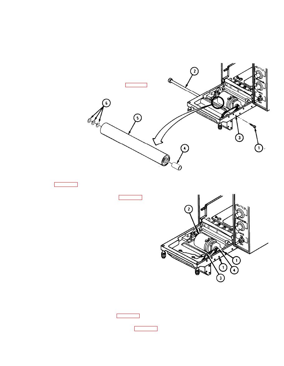
INSTALLING GUIDE ROLLER ASSEMBLY |
|
||
| ||||||||||
|
|
 TM 11-7025-217-30
INSTALLING GUIDE ROLLER ASSEMBLY
2-49.
Aline shaft (2) with mounting hole on door (3).
1.
Slide shaft (2) through door (3) and install shims (6), guide roller (5), and bushing (4).
2.
Install screw (1).
3,
4.
Install spring loaded roller assembly (para 2-45).
REMOVING DRIVE BELT
2-50.
1.
Remove spring loaded roller assembly
Remove drive roller assembly (para 2-46).
2.
Loosen two screws (1) two turns.
3.
4.
Slide motor assembly (2) back and remove
drive belt (3) from motor drive spur (4).
INSTALLING DRIVE BELT
2-51.
Put drive belt (3) over motor drive spur (4).
1.
CAUTION
Use care not to pinch wires that are routed under motor assembly.
Move motor (2) to put tension on drive belt, then tighten two screws (1)
2.
Install drive roller assembly (para 2-47).
3.
Install spring loaded roller assembly (para 2-45).
4.
2-91
|
|
Privacy Statement - Press Release - Copyright Information. - Contact Us |
