 |
|||
|
|
|||
|
Page Title:
REMOVING SPRING LOADED ROLLER ASSEMBLY |
|
||
| ||||||||||
|
|
 TM 11-7025-217-30
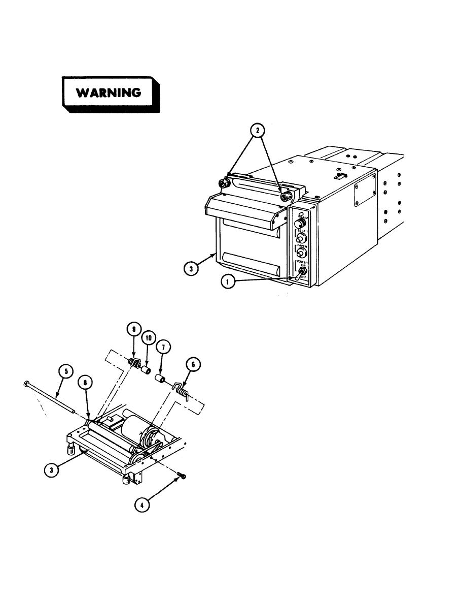
REMOVING SPRING LOADED ROLLER ASSEMBLY
2-44.
Turn off power before working on
equipment. Failure to do so can
cause serious injury to personnel.
1. Set POWER ON/OFF circuit
breaker (1) to OF F.
Disconnect printer from power
2.
source.
3.
Loosen two captive thumbscrews
(2) and open door (3). Remove
paper and spool. (Refer to
TM 11-7021-201-12.)
4.
Remove screw (4).
CAUTION
Roller is spring loaded. Use care
when removing it from door.
Use care not to damage threads
when driving shaft out of door
frame.
Using a 1/16-inch drift pin, drive
5.
shaft (5) through mounting hole of
door (3) until shaft clears inside of
door.
6. Working from left side of door (3),
pull shaft (5) through door and remove
right tension spring (6), bushing (7),
roller frame assembly (8), left tension
spring (9), and bushing (10).
NOTE
If washers are used, note position and
reinstall during reassembly.
USE OR DISCLOSURE OF THIS DATA IS SUBJECT TO THE RESTRICTION ON PAGE D OF THIS DOCUMENT.
2-84
|
|
Privacy Statement - Press Release - Copyright Information. - Contact Us |
