 |
|||
|
|
|||
|
|
|||
| ||||||||||
|
|
 TM 11-7025-217-30
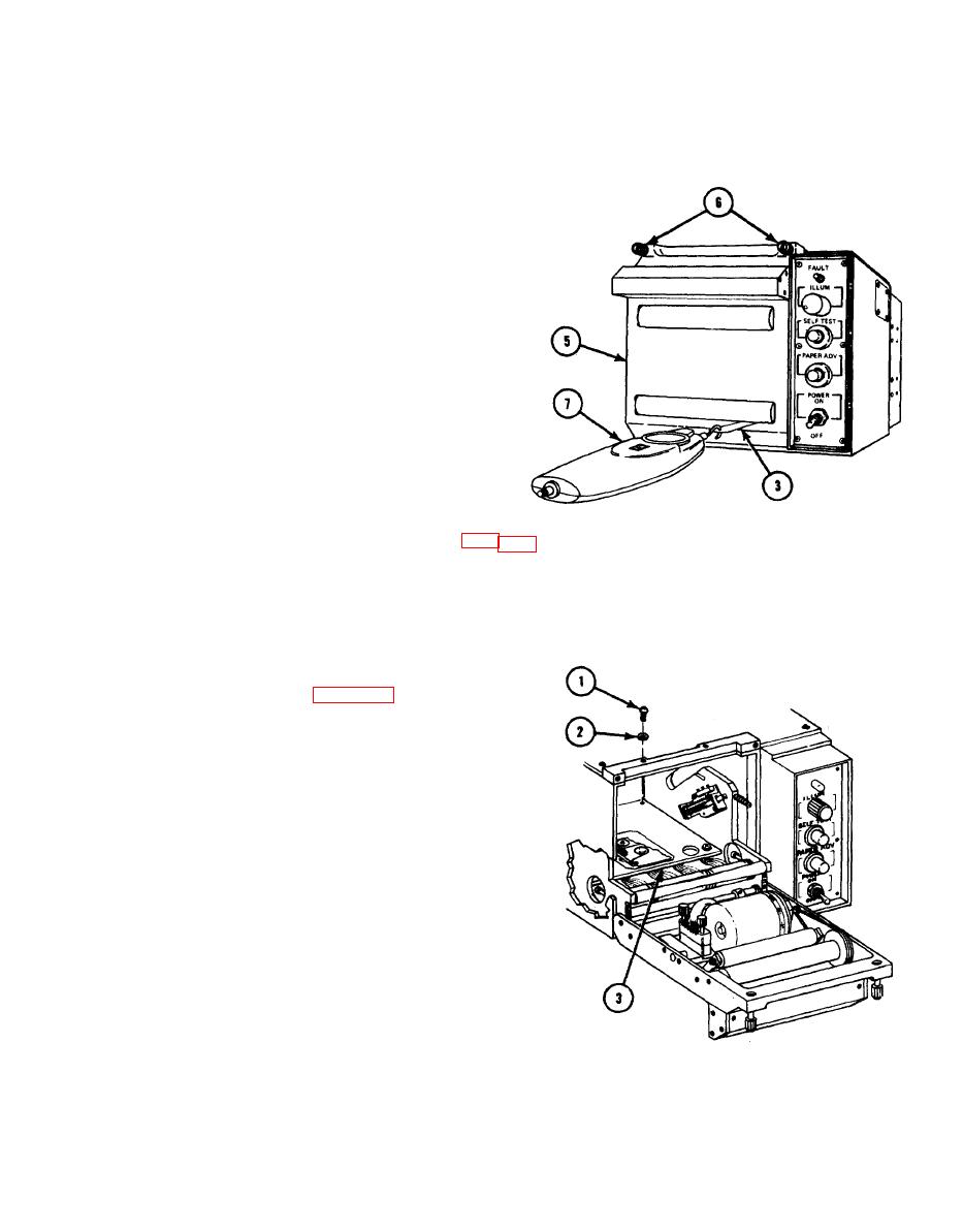
6. Close door (5) and tighten two captive thumbscrews (6).
7,
Attach hooked end of dial pressure gage (7) to reinforcement tab on pressure test tool (3) as
shown.
8.
Holding dial pressure gage (7) Ievel,
pull pressure test tool (3) straight out
of door (5). Note readout on dial
pressure gage.
Repeat steps 4 thru 8 until same
9.
reading is obtained on two consecutive
measurements.
10.
Repeat steps 4 thru 9 for left end of
printhead (1).
11.
If readings noted on dial pressure gage
(7) for the left and right ends of
printhead are between 3.7 ounces (105
grams) and 4.8 ounces (135 grams), and
within 0.75 to 1.0 ounce (20 to 30
grams) of each other, no adjustment is
necessary. If readings are not within
12
If readings are within limits, install paper and spool. (Refer to TM 11-7021 -201-12.)
2-29. PRINTHEAD PRESSURE ADJUSTMENT
1. Remove top cover (para 2-26).
2. Remove four screws (l), four flatwashers
(2), and protective cover (3).
NOTE
To adjust pressure, turn adjustment
screws 1/2 turn at a time.
CAUTION
While adjusting screws, use care not
to contact wire wrap pins on
motherboard. Pins can be easily
damaged or broken.
2-71
|
|
Privacy Statement - Press Release - Copyright Information. - Contact Us |
