 |
|||
|
|
|||
|
Page Title:
MOTOR/TAKE-UP CABLE ASSEMBLY CONTINUITY TEST |
|
||
| ||||||||||
|
|
 TM 11-7025-217-30
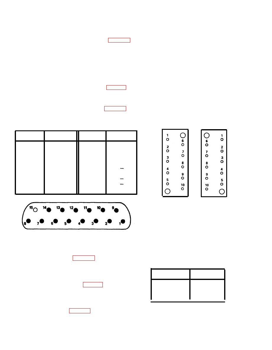
MOTOR/TAKE-UP CABLE ASSEMBLY CONTINUITY TEST
2-21.
1.
Remove motor/take-up cable assembly (para 2-74).
2. Check cable assembly for bare wires, physical damage, and shorts between pins.
NOTE
Use a spare connector pin as an aid when making continuity
checks.
3.
Measure continuity of cable assembly (table 2-8).
4.
If wiring problems exist, repair or replace assembly as required,
Install motor/take-up cable assembly (para 2-75).
5.
TABLE 2-8. MOTOR/TAKE-UP CABLE ASSEMBLY
CONTINUITY TEST
FROM
FROM
TO
TO
P5-1
P5-8
J9-6
P10-5
P5-2
P5-9
P10-2
Shield
P5-3
P5-10
P10-10
P10-9
P5-11
P5-4
P10-3
J9-5
P5-12
P5-5
P10-6
P5-13
P5-6
J9-2
J9-3
P5-14
P5-7
P10-4
P5-15
J9-4
Shield
CONNECTOR
CONNECTOR
P10
J9
CONNECTOR
P5
2-22.
POWER CABLE CONTINUITY TEST
1.
Remove power cable (para 2-72).
TABLE 2-9. POWER CABLE
CONTINUITY TEST
2. Check cable for bare wires, physical damage,
and shorts between terminals.
FROM
TO
3. Check continuity of cable (table 2-9).
E2
E5
E3
E6
4.
If wiring problems exist, repair or replace
E4
E7
cable as required.
Install power cable (para 2-73).
5.
2-66
|
|
Privacy Statement - Press Release - Copyright Information. - Contact Us |
