 |
|||
|
|
|||
|
|
|||
| ||||||||||
|
|
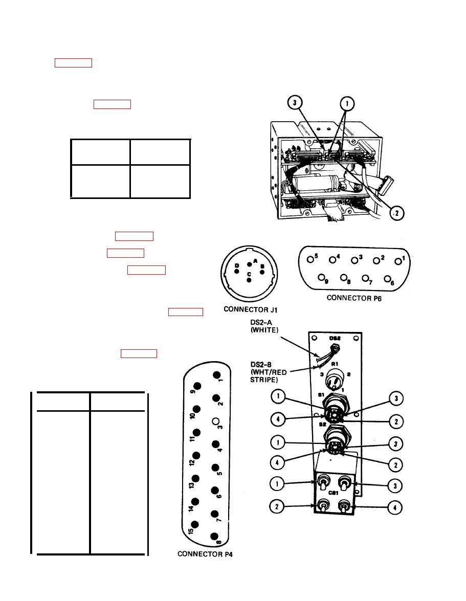 TM 11-7025-217-30
5, If wiring problems exist, remove input power filter assembly
6. Aline connector P6(2) to connector J6(3) and tighten two screws
(1), two turns at a time, until connector is tight.
7. Join chassis (para 2-31).
TABLE 2-5. INPUT POWER FILTER ASSEMBLY
CONTINUITY TEST
FROM J1
TO P6
PIN NO.
PIN NO.
A
6,7,8,9
B
1,2,3,4
C
CHASSIS
2-19.
CONTROL PANEL CONTINUITY TEST
1.
Remove top cover (para 2-26).
2. Separate chassis (para 2-30).
3.
Remove control panel (para 2-32).
4. Check control panel harness for bare wires,
physical damage, and shorts between pins.
5. Check continuity of control panel (table 2-6).
6.
If wiring problems exist, repair or replace
control panel,
Install control panel (para 2-33).
7.
TABLE 2-6. CONTROL PANEL
CONTINUITY TEST
FROM
TO
P4-1
DS2-A
P4-2
DS2-B
P4-3
Key
P4-4
CB1-2
P4-5
C81-1
P4-6
CB1-3
P4-7
CB1-3
P4-8
S1-3
P4-9
R 1-3
P4-10
R1-2
P4-11
R1-1
P4-12
S1-4
S1-4
S2-4
P4-13
S2-3
P4-14
CB1-4
P4-15
CB1-4
2-64
|
|
Privacy Statement - Press Release - Copyright Information. - Contact Us |
