 |
|||
|
|
|||
|
Page Title:
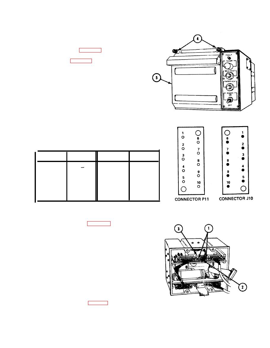
INPUT POWER FILTER ASSEMBLY CONTINUITY TEST |
|
||
| ||||||||||
|
|
 TM 11-7025-217-30
12. Close door (5) and tighten two captive
thumbscrews (4).
13. Install top cover (para 2-27).
14. Join chassis (para 2-31).
TABLE 2-4. MOTOR HARNESS ASSEMBLY
CONTINUITY TEST
TO
FROM
TO
FROM
P11-6
J10-6
J10-1
--
J10-7
P11-2
J10-2
--
J10-8
P11-3
J10-3
P11-9
J10-9
P11-4
J10-4
P11-10
J10-10
P11-5
J10-5
2-18. INPUT POWER FILTER ASSEMBLY CONTINUITY TEST
Separate chassis (para 2-30).
1.
Loosen two screws (1), turning each screw
2.
two turns at a time, until connector P6(2)
can be removed from connector J6(3).
Check input power filter assembly harness
3.
for bare wires, physical damage, and shorts
between pins of connector J1.
NOTE
Use a spare connector pin as an aid when
making continuity checks.
Check continuity (table 2-5).
4.
2-63
|
|
Privacy Statement - Press Release - Copyright Information. - Contact Us |
