 |
|||
|
|
|||
|
Page Title:
MOTOR HARNESS ASSEMBLY CONTINUITY TEST |
|
||
| ||||||||||
|
|
 TM 11-7025-217-30
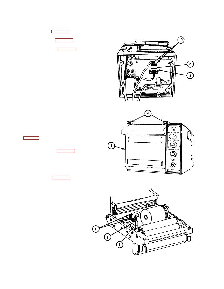
MOTOR HARNESS ASSEMBLY CONTINUITY TEST
2-17.
1.
Separate chassis (para 2-30).
Remove top cover (para 2-26).
2.
3.
Remove logic board (para 2-54).
4.
Loosen two screws (1), turning each screw
two turns at a time, until connector
P10(2) can be removed from connector
J10(3).
5.
Loose two captive thumbscrews (4) and
open door (5).
6.
Loosen two screws (6), turning each screw
two turns at a time, until connector P11(7)
can be removed from connector J11(8).
NOTE
Use a spare connector pin as an aid when
making continuity checks.
7.
Measure continuity of harness assembly
8.
If wiring problems exist, repair or replace
assembly as required (para 2-62 and 2-63).
9.
Aline connector P10(2) with connector
J10(3) and tighten two screws (1), two
turns at a time, until tight.
10.
Install logic board (para 2-55).
11.
A line connector P11(7) with connector
J11(8) and tighten two screws (6), two
turns at a time, until connector is tight,
2-62
|
|
Privacy Statement - Press Release - Copyright Information. - Contact Us |
