 |
|||
|
|
|||
|
Page Title:
INPUT DATA CABLE ASSEMBLY CONTINUITY TEST |
|
||
| ||||||||||
|
|
 TM 11-7026-217-30
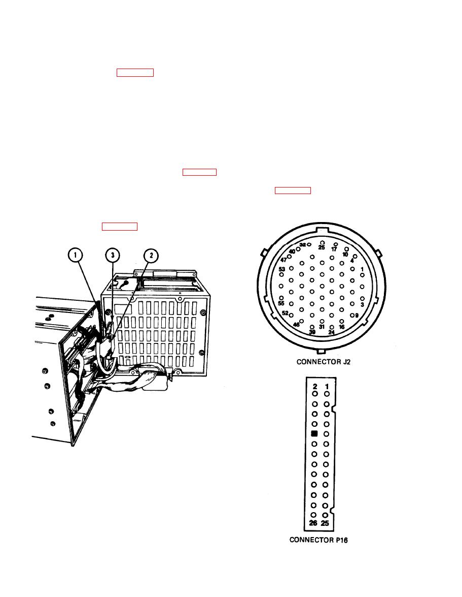
INPUT DATA CABLE ASSEMBLY CONTINUITY TEST
2-15.
1.
Separate chassis (para 2-30).
2.
Check cable assembly for bare wires, physical damage, and shorts between pins.
Open clamp (1) and remove connector P16 (2) from connector J16 (3).
3.
NOTE
Use a spare connector pin as an aid when making continuity
checks.
4.
Check continuity of cable assembly (table 2-2).
5.
If wiring problems exist, repair or replace assembly as required (para 2-70 and 2-71).
6.
Aline and mate connector P16 (2) to connector J16 (3), Close clamp (1) to secure connectors.
7.
Join chassis (para 2-31).
2-58
|
|
Privacy Statement - Press Release - Copyright Information. - Contact Us |
