 |
|||
|
|
|||
|
Page Title:
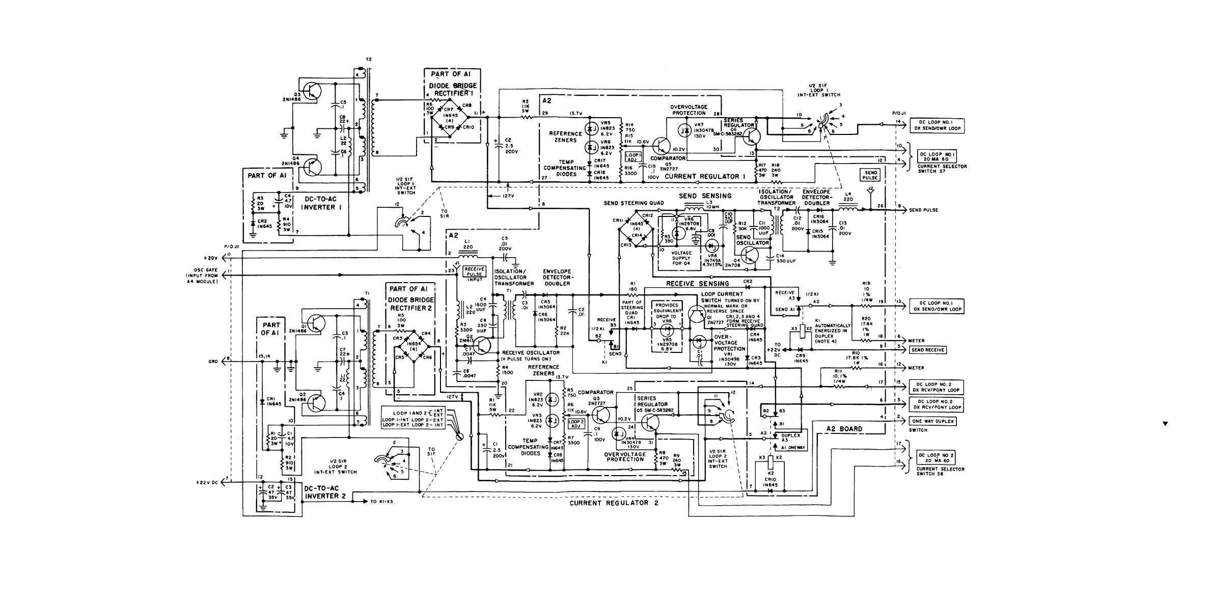
Figure FO-9. Loop Battery A5 Module, Schematic Diagram. |
|
||
| ||||||||||
|
|
 TM 11-5805-387-34-2
NOTES:
1
ALL RESISTOR VALUES ARE IN OHMS, CAPACITORS IN UF, AND
INDUCTORS IN UH UNLESS OTHERWISE SPECIFIED
2
ALL SWITCHES ARE SHOWN IN CCW POSITION
3
HEAVY LINES SHOW MAIN SIGNAL PATH FOR DUPLEX OPERATION,
USING INTERNAL 20 MA SUPPLY. DC FLOW IS FROM + TO -, AND IS
SHOWN BY AN OPEN ARROWHEAD: ∇ DIRECTION OF SEND AND
RECEIVE PULSES ARE SHOWN BY A CLOSED ARROWHEAD:
4
KI IS SHOWN IN THE ENERGIZED POSITION
5
VOLTAGE TOLERANCE OF ZENERS WITH " "SUFFIX IS 5%, WITH
B
NO SUFFIX. 10%
Figure FO-9. Loop Battery A5 Module, Schematic Diagram.
|
|
Privacy Statement - Press Release - Copyright Information. - Contact Us |
