 |
|||
|
|
|||
|
|
|||
| ||||||||||
|
|
 TM 11-5805-387-34-2
3-7. TEST POINT MEASUREMENTS
CAUTION
Do not short the test point jacks to the modem chassis. This could cause equipment damage.
General Instructions
Test equipment: See paragraph 2-2.
Bench setup and test conditions: See paragraph 2-4.
Procedures
The values listed in the charts below are for troubleshooting purposes only; they represent average
values measured at designated test points.
Use the signal generator for MODEM INPUT.
Use the voltmeter to measure across test points.
Test Point Charts
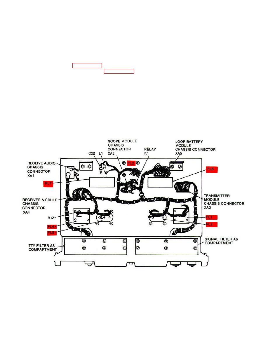
Test point chart 2: Front panel and chassis test points.
Test point chart 3: Transistor Q1, Q2, Q3 voltage chart.
3-19
|
|
Privacy Statement - Press Release - Copyright Information. - Contact Us |
