 |
|||
|
|
|||
|
Page Title:
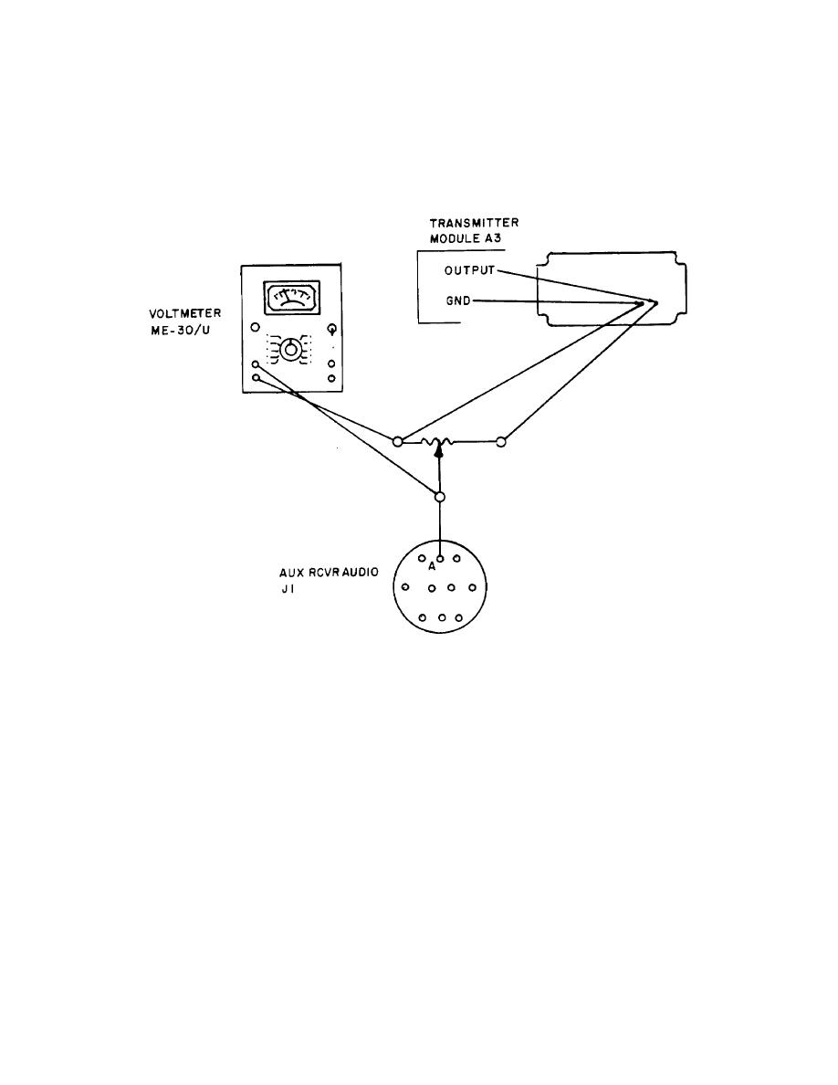
SCOPE MODULE A2 ALIGNMENT (Cont) |
|
||
| ||||||||||
|
|
 TM 11-5805-387-34-2
PROCEDURE
INDICATION
NO
8. Use the ME-301U to measure the voltage
9 mv rms
between the wiper of the test potentiometer
connected to transmitter module A3 and the
terminal of the test potentiometer connected
to the GRD test point. Adjust the test poten-
tiometer.
9. Adjust SQUELCH ADJ potentiometer
Pattern disappears
A2A1 R25.
10. Readjust test potentiometer.
11 mv rms (pin A of J1),
Adjust
Pattern reappears
SQUELCH
ADJ. Repeat
steps 8, 9, 10
with 9 to 11
mv rms at pin
A of J1.
11. Set ON/OFF switch OFF. Turn off power to
all test equipment. Replace metal cover over
component board A2A1.
2-41
|
|
Privacy Statement - Press Release - Copyright Information. - Contact Us |
