 |
|||
|
|
|||
|
|
|||
| ||||||||||
|
|
 TM 11-5805-387-34-2
2-18. SCOPE MODULE A2 ALIGNMENT
Teat Equipment
Teletypewriter Test Set TS-799AIUGM-1
Multimeter ME-26BIU
Voltmeter ME-301U
Test Potentiometer, 600-ohms, 1/2-watt
Extender Cable
Test Connections
Perform the centering adjustment (para 2-17)
Make sure ON/OFF switch is in OFF position.
Remove scope module A2 and connect extender cable.
Remove metal cover on the left side of the module protecting component board Al.
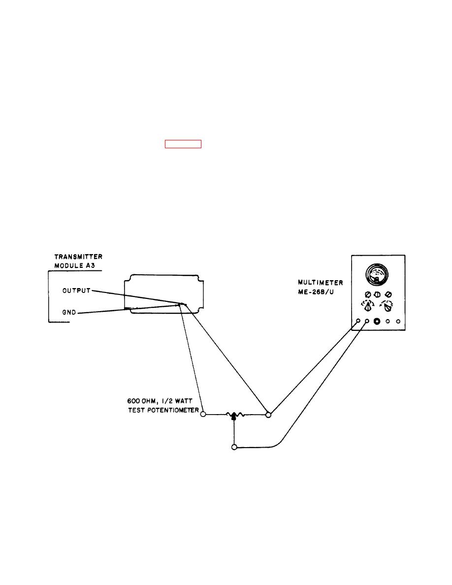
Connect a 600-ohm, 1/2-watt test potentiometer between OUTPUT and GRD test points on transmitter
module A3.
Measuring with the multimeter, adjust the test potentiometer for minimum resistance between the wiper
and the terminal connected to the OUTPUT test point.
Connect the wiper of the test potentiometer to pin A of AUX RCVR AUDIO connector J1.
Adjust TS-799A/UGM-1 to operate on external loop power (supplied from the modem) and to supply an
R and Y test signal.
2-39
|
|
Privacy Statement - Press Release - Copyright Information. - Contact Us |
