 |
|||
|
|
|||
|
|
|||
| ||||||||||
|
|
 TM 11-5805-387-34-2
PROCEDURE
INDICATION
NO
1. Set power ON/OFF switch to ON.
+ 22 volts dc 0.2
Go to 2
2. Adjust +22 V ADJ potentiometer A9R11 until
multimeter reading is correct.
3. Connect multimeter's positive probe to
+ 20 volts dc 0.1
Go to 4
+20V REG test point on module A1.
4. Adjust +20 V REG ADJ potentiometer
A1A2R4 until meter reads 20 vdc 0.1
5. Set ON/OFF switch to OFF. Disconnect test
setup.
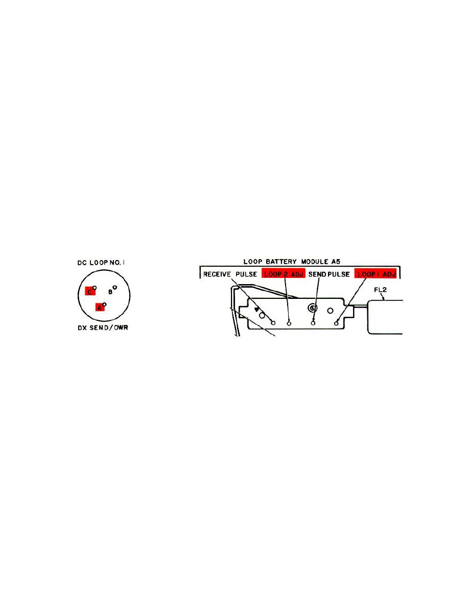
2-15. LOOP CURRENT ADJUSTMENT
Test Equipment
Multimeter TS-352B/U (set up for current measurement)
Test Connections
Connect multimeter's positive lead to pin A of DC LOOP NO. 1 DX SENDIOWR connector J6. Connect
ground lead to pin C of connector J6.
Remove dust cover from loop battery module A5.
Modem Settings
CONTROL OR SWITCH
SETTING
MODE SELECTOR
85 HZ
AUTO MARK HOLD
ON
SCOPE INTENSITY
FULLY CCW
2-35
|
|
Privacy Statement - Press Release - Copyright Information. - Contact Us |
