 |
|||
|
|
|||
|
|
|||
| ||||||||||
|
|
 TM 11-5805-387-34-2
Test cable No. 3 is to be constructed to permit back-to-back operation of the modem for testing. It connects the
output of the transmit section of the modem to the input of the receive section.
Cable: 17-inch length of No. 24 ASW single-conductor stranded cable.
Connectors: NSN 5935-00-762-1495 J1
NSN 5935-00-771-2262 J2
Connect one end of cable to pin J of connector 6612 MS 3116 F12-10P and the other end to pin A of connector
6612 MS 3116 F12-10S. Connect a one-quarter inch wire between pins B and D of 6612 MS 3116 F12-10P.
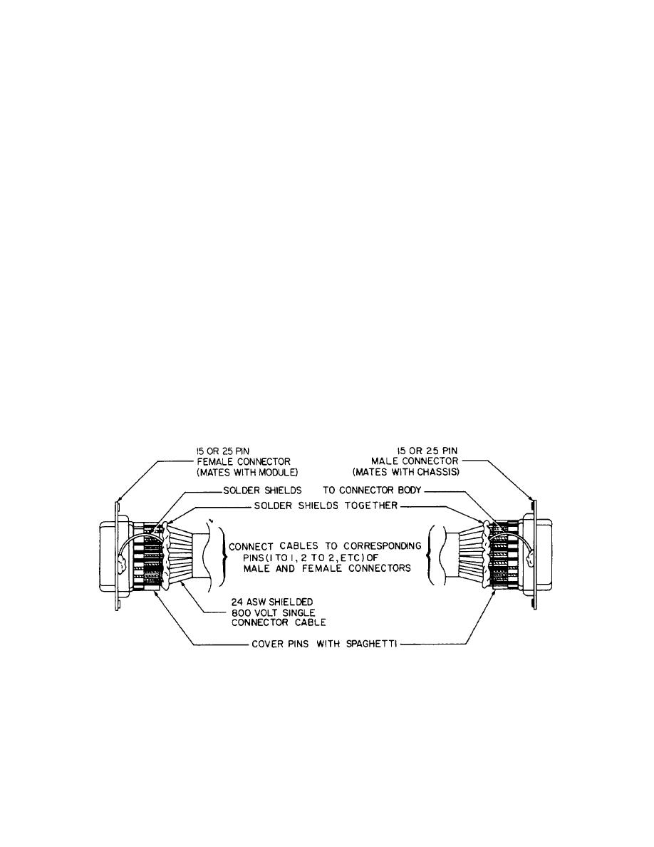
OPTIONAL MATERIALS
Extender test cables may be needed to reach operating modem modules. Construct these cables If you need
them. Construct at least one 15-pin and one 25-pin test cable.
Cable: 3-foot lengths of No. 24 ASW shielded single-conductor stranded audio cable.
Connectors: NSN 5935-00-914-2287 A3J1
NSN 5935-00-930-7025 A1J1
NSN 5935-00-930-7026 XA1
NSN 5935-00-880-2884 XA3
Strip shielding back 1 inch from female connector on both test cables. Connect shields at male end to a heavy bus
that can be secured to the modem chassis common ground point.
EXTENDER CABLE
2-3
|
|
Privacy Statement - Press Release - Copyright Information. - Contact Us |
