 |
|||
|
|
|||
|
Page Title:
Adjusting L oop Current Internal/External Switch |
|
||
| ||||||||||
|
|
 TM 11-5805-387-20-2
d. Preliminary Servicing and Adjustment of Equipment
Make initial adjustments after installing modem but before beginning routine operation,
NOTE
The following adjustments can only be made with modem chassis removed
from its case (para 2-9).
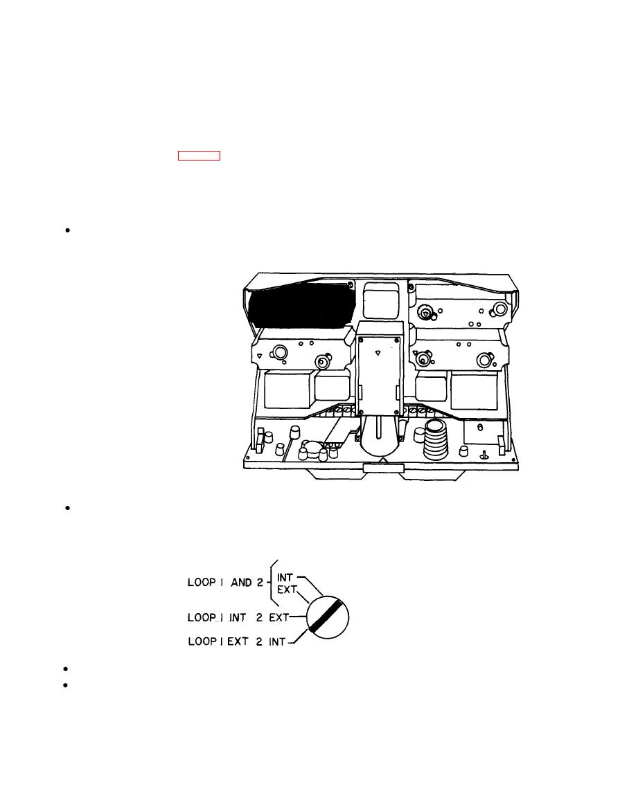
e. Adjusting L oop Current Internal/External Switch
. Current for dc loop No. 1 and dc loop No. 2 may be supplied by internal loop battery module
A5 (see figure) or by external means.
CHASSIS INTERIOR, TOP VIEW
Internal/External switch A5S1 is a screwdriver adjustment on top of module A5 which sets the
appropriate sources of current for dc loops No. 1 and No. 2. See figure for settings provided.
A5S1 is normally set at LOOP 1 AND 2 INT when modem is shipped from the factory.
Set A5S1 according to desired sources of loop current for dc loops No. 1 and 2.
|
|
Privacy Statement - Press Release - Copyright Information. - Contact Us |
